Industrial Radar Sensors
Industrial Radar Sensors
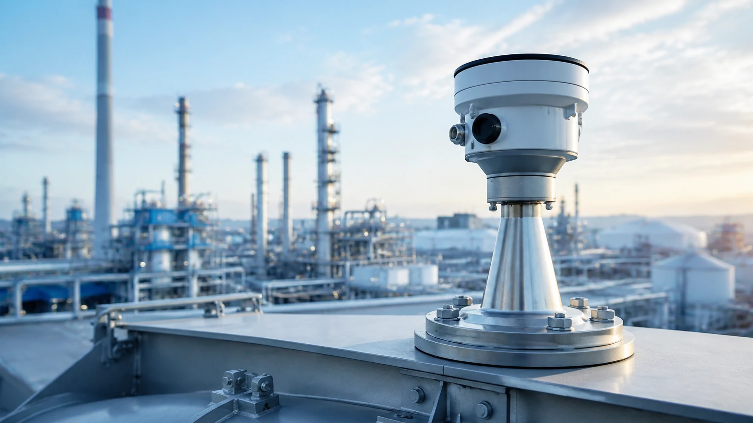
In the landscape of modern process automation, industrial radar sensors have emerged as the gold standard for non-contact level measurement. These instruments utilize electromagnetic waves to determine the distance to a product surface, providing high-precision data that is essential for inventory management, process control, and safety across industries such as chemical processing, water treatment, oil and gas, and food production. Unlike ultrasonic sensors, which rely on sound waves and are susceptible to changes in air temperature or pressure, radar technology remains stable under extreme process conditions.
Selecting the appropriate level measurement solution requires a deep understanding of how these sensors interact with the environment. As a professional manufacturer, Welk provides a comprehensive range of level measurement instruments, and detailed specifications can be found on our Main Page.
Measurement Principles: How Industrial Radar Sensors Work
Industrial radar sensors operate on the principle of Time of Flight (ToF). The sensor emits a microwave signal toward the medium, which reflects off the surface and returns to the antenna. By measuring the time elapsed between emission and reception, the device calculates the distance. There are two primary methods used in industrial applications: Pulse Radar and Frequency Modulated Continuous Wave (FMCW).
Pulse Radar Technology
Pulse radar sensors emit short microwave pulses at a fixed frequency. The device measures the time it takes for a single pulse to travel to the surface and back. While effective and energy-efficient, pulse radar often has a lower signal-to-noise ratio compared to FMCW, making it more suitable for simpler applications with clear surface reflections and fewer internal tank obstructions.
FMCW (Frequency Modulated Continuous Wave)
FMCW radar is the preferred technology for complex industrial environments. Instead of sending discrete pulses, the sensor transmits a continuous signal while constantly varying the frequency (sweep). The reflection from the product surface arrives at the antenna with a different frequency than the one currently being transmitted. The difference between these frequencies ($Δf$) is directly proportional to the distance. FMCW offers superior accuracy and better signal processing capabilities, allowing the sensor to filter out "false echoes" caused by agitators, ladders, or internal bracing.
The Role of Frequency in Radar Performance
The frequency at which industrial radar sensors operate significantly influences their beam angle, sensitivity, and ability to penetrate vapor or foam. Most industrial units operate in three main bands: 6GHz, 26GHz, and 80GHz.
1. 6GHz Radar (C-Band): Known for its long wavelength, 6GHz radar is highly effective in applications involving heavy steam, condensation, or foam. The longer waves can penetrate these surface disturbances more effectively than higher frequencies. However, they require larger antennas to maintain a focused beam.
2. 26GHz Radar (K-Band): This is the "all-rounder" of the industry. It offers a balance between a relatively narrow beam and good resistance to process conditions. It is widely used in both liquid and solid level measurement where the tank height is moderate (up to 30 meters / 98 feet).
3. 80GHz Radar (W-Band): The current state-of-the-art in level measurement. 80GHz sensors provide an extremely narrow beam angle (often as small as 3 degrees). This precision allows the sensor to be installed in small nozzles or in tanks with complex internal structures without interference. It also offers the highest resolution, making it ideal for high-accuracy custody transfer applications.
Key Evaluation Criteria for Selection
When specifying industrial radar sensors for a project, engineers must evaluate several physical and chemical factors to ensure long-term reliability.
Dielectric Constant (εr)
The dielectric constant of the medium is the most critical factor in radar measurement. It represents the ability of a material to reflect electromagnetic waves.
* High εr (>10): Water-based liquids reflect signals strongly, making them easy to measure.
* Low εr (1.4 to 4): Hydrocarbons, oils, and some solids reflect very little energy. In these cases, a more sensitive FMCW radar or a guided wave radar (GWR) may be required to ensure a stable signal.
Process Temperature and Pressure
Radar sensors are designed with specific sealing technologies to withstand extreme environments. Standard units typically handle up to 150°C (302°F), but specialized high-temperature versions can operate in environments exceeding 400°C (752°F). Similarly, pressure ratings can range from vacuum conditions to over 100 bar (1450 psi).
Vessel Geometry and Internal Obstructions
The presence of heating coils, agitators, or reinforcement beams can create false reflections. Selecting a sensor with a narrow beam angle (such as 80GHz) or advanced software echo-mapping is essential to ignore these static objects and focus solely on the product level.
Practical Selection Table
| Application Type | Recommended Frequency | Key Advantage | Typical Industry |
| :— | :— | :— | :— |
| Large Storage Tanks (Liquids) | 80GHz | High accuracy, narrow beam | Oil & Gas, Chemical |
| Corrosive Acids/Bases | 26GHz / 80GHz | Non-contact, PTFE flange covers | Chemical Processing |
| Heavy Steam/Vapor | 6GHz | Signal penetration | Power Generation |
| Solids/Powders (Silos) | 80GHz | Penetrates dust, handles steep angles | Cement, Mining |
| Small Process Vessels | 80GHz | Fits small nozzles | Pharmaceutical, F&B |
Installation and Engineering Guidelines
Correct installation is as important as selecting the right technology. Failure to follow basic engineering principles can lead to signal loss or erratic readings.
* Nozzle Dimensions: The radar antenna should ideally extend slightly beyond the bottom of the mounting nozzle to prevent signal interference from the nozzle walls. If the nozzle is very long, a higher frequency (80GHz) is recommended due to its narrow beam.
* Avoid the Center: In cylindrical tanks with domed tops, do not install the sensor in the exact center. This can cause a "parabolic effect," where multiple reflections from the tank walls converge and overwhelm the sensor.
* Obstruction Clearance: Maintain a clear "keep-out zone" for the radar beam. The beam expands as it travels; for a 10-degree beam angle, the beam diameter will be approximately 1.7 meters (5.6 feet) at a distance of 10 meters (33 feet).
* Agitator Interference: If the tank has an agitator, the sensor should be mounted in a position where the beam does not hit the blades directly. Modern industrial radar sensors include "false echo suppression" software to learn the position of the blades and ignore them during measurement.
Common Risks and Limitations
While industrial radar sensors are incredibly versatile, they are not universal solutions. Engineers should be aware of the following limitations:
1. Heavy Foam: While 6GHz can penetrate some foam, extremely thick, dense foam (like shaving cream) can absorb the radar signal entirely. In these specific cases, a magnetic level gauge or a hydrostatic transmitter might be more reliable.
2. Extremely Low Dielectric Solids: Very light plastic pellets or powders with a dielectric constant below 1.4 may not reflect enough energy for a non-contact radar. Guided wave radar, which uses a physical probe to direct the signal, is often a better choice here.
3. Antenna Buildup: In applications with heavy crystallization or sticky media, material can build up on the antenna. While many radar sensors feature a "lens" design that sheds droplets, significant buildup will eventually attenuate the signal, requiring periodic cleaning or the use of a purging connection.
Frequently Asked Questions (FAQ)
Q: Can industrial radar sensors measure through plastic tank walls?
A: Yes. Because plastic is non-conductive and has a low dielectric constant, radar signals can often pass through the top of a plastic IBC or tank to measure the liquid inside without a hole being cut in the vessel.
Q: What is the difference between Radar and Ultrasonic sensors?
A: Radar uses electromagnetic waves (light speed), while ultrasonic uses sound waves. Radar is unaffected by air temperature, pressure, vacuum, or vapor, making it much more reliable for industrial process tanks than ultrasonic technology.
Q: Is 80GHz always better than 26GHz?
A: Not necessarily. While 80GHz offers a narrower beam and better accuracy, 26GHz is often more cost-effective for simple applications and can be more robust in certain types of heavy dust or condensation where the slightly longer wavelength is an advantage.
Q: How do I handle a tank with a vacuum?
A: Radar is the ideal technology for vacuum applications. Since electromagnetic waves do not require a medium to travel (unlike sound), the accuracy of a radar sensor remains unchanged in a vacuum.
Conclusion
Industrial radar sensors represent a significant investment in process efficiency and safety. By understanding the principles of FMCW technology, the impact of frequency, and the specific requirements of the medium being measured, facilities can achieve maintenance-free level monitoring for years. Whether dealing with corrosive chemicals or bulk solids in a silo, there is a radar configuration designed to meet the challenge. For assistance in selecting the specific model for your application, including radar, ultrasonic, or hydrostatic options, please visit our Main Page to review product options and application support.