Emerson Ultrasonic
Emerson Ultrasonic
In the landscape of industrial automation and process control, ultrasonic level measurement remains a cornerstone technology for non-contact monitoring of liquids and solids. Among the industry leaders, Emerson ultrasonic solutions—primarily under the Rosemount brand—are recognized for their reliability in diverse environments ranging from municipal water treatment to complex chemical processing. Selecting the right ultrasonic instrumentation requires a deep understanding of the underlying physics, the specific capabilities of the hardware, and the environmental factors that can influence measurement accuracy.
This guide provides a technical overview of ultrasonic level measurement principles, evaluates the Emerson ultrasonic portfolio, and outlines critical selection and installation criteria for engineering professionals.
Understanding Ultrasonic Level Measurement Principles
Before evaluating specific hardware like Emerson ultrasonic transmitters, it is essential to understand the operational physics of ultrasonic technology. These instruments operate on the Time-of-Flight (ToF) principle, a method that relies on the propagation of sound waves through a medium (usually air).
The Time-of-Flight (ToF) Method
An ultrasonic sensor contains a piezoelectric crystal that acts as both a transmitter and a receiver. The sensor emits a high-frequency acoustic pulse—typically between 20 kHz and 200 kHz—which travels through the tank headspace until it hits the surface of the process media. The pulse is reflected back to the sensor as an echo.
The transmitter measures the time interval between the emission of the pulse and the reception of the echo. Since the speed of sound in air is known, the distance to the surface can be calculated using the formula:
Distance = (Speed of Sound × Time Delay) / 2
The level of the material is then determined by subtracting this distance from the total tank height (the calibration point). Manufacturers like Welk and Emerson integrate sophisticated algorithms to filter out "false echoes" caused by internal tank obstructions, such as agitators or ladders.
Temperature and Atmospheric Compensation
The speed of sound is not constant; it varies significantly with the temperature of the medium through which it travels. For instance, in air, the speed of sound changes by approximately 0.17% per degree Celsius. To maintain accuracy, industrial ultrasonic sensors include an integrated temperature sensor to provide real-time compensation. In applications with significant temperature gradients, external temperature sensors may be required to provide a more representative average of the headspace temperature.
Emerson Ultrasonic Product Range: Features and Capabilities
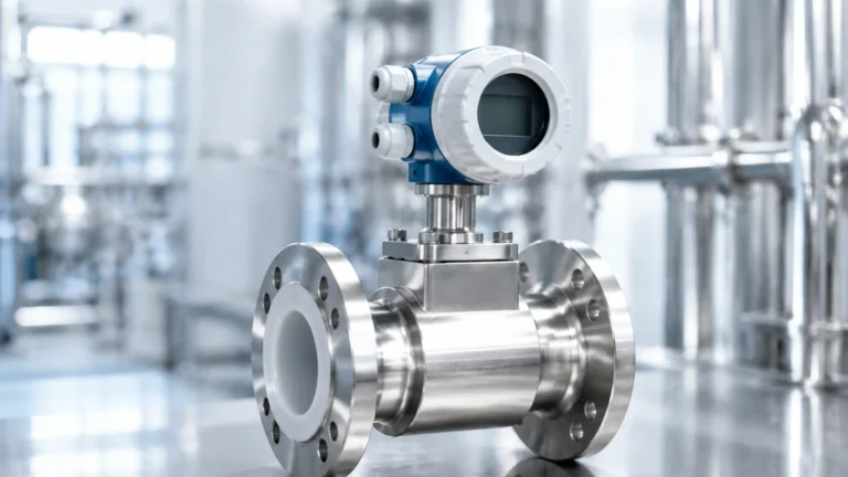
Emerson’s ultrasonic portfolio is designed to address a spectrum of industrial needs, from simple level detection to complex volume and flow calculations in open channels. The Rosemount series is the primary vehicle for these solutions.
Rosemount 3100 Series
The Rosemount 3100 series represents the core of the Emerson ultrasonic lineup. These liquid level transmitters are designed for reliability and ease of use:
* Rosemount 3101: A basic, cost-effective solution for simple level measurement with a range of up to 8 meters (26 feet). It provides a 4-20mA output.
* Rosemount 3102 and 3105: These models offer advanced functionality, including HART communication and integrated software for volume calculations (e.g., for horizontal tanks) and open channel flow measurement (using flumes and weirs). The 3105 is often used in more demanding chemical environments due to its material construction options.
Rosemount 3490 Series Controllers
While many Emerson ultrasonic sensors are self-contained transmitters, the 3490 series controllers provide a dedicated interface for wall or panel mounting. These controllers power the transmitters and provide advanced data logging, pump control logic (such as lead-lag sequencing), and multi-relay outputs for alarm management. This is particularly useful in wastewater lift stations where automated pump control is critical.
Key Evaluation Criteria for Industrial Ultrasonic Sensors
When specifying an ultrasonic instrument, engineers must look beyond the brand name and evaluate the technical specifications against the application requirements. Whether considering Emerson ultrasonic units or alternatives from professional manufacturers like Welk, the following criteria are paramount:
1. Measurement Range: Ensure the sensor’s effective range covers the full depth of the tank, including a safety margin. Most industrial units range from 0.3m (1ft) to 12m (40ft).
2. Chemical Compatibility: The transducer face (the wetted part) must be resistant to the process vapors. Common materials include UPVC, Polypropylene, and PVDF (Kynar).
3. Output Requirements: Standard 4-20mA is common, but digital protocols like HART, Modbus, or Profibus are often required for integration into modern DCS or SCADA systems.
4. Accuracy and Resolution: High-precision applications (like custody transfer or chemical dosing) require sensors with lower margin of error, typically ±0.05% to ±0.25% of the measured distance.
Selection Table for Ultrasonic Level Transmitters
The following table provides a general comparison of typical specifications found in professional-grade ultrasonic level meters, similar to those offered by Emerson and Welk.
| Feature | Entry-Level (e.g., 3101) | Mid-Range (e.g., 3102) | High-Performance (e.g., 3105) |
| :— | :— | :— | :— |
| Max Range | 8 meters (26 ft) | 11 meters (36 ft) | 12 meters (40 ft) |
| Accuracy | ±0.25% of span | ±0.1% of span | ±0.05% of span |
| Communication | 4-20 mA | 4-20 mA + HART | 4-20 mA + HART / Fieldbus |
| Housing Material | Nylon / Polycarbonate | Glass-filled Nylon | Aluminum or Stainless Steel |
| Wetted Materials | UPVC | UPVC / Fluro-polymer | PVDF (Kynar) |
| Diagnostics | Basic Echo Loss | Advanced Echo Processing | Full Diagnostic Suite |

Installation Best Practices and Considerations
Even the most advanced Emerson ultrasonic transmitter will fail to provide accurate data if installed incorrectly. Proper mechanical installation is the most critical factor in system performance.
Beam Angle and Obstruction Management
Ultrasonic pulses do not travel in a straight line; they spread out in a cone shape, known as the beam angle. This angle typically ranges from 5 to 12 degrees. It is vital to ensure that no physical obstructions (pipes, agitators, or wall seams) enter this cone, as they will create "parasitic echoes" that the transmitter might mistake for the material level.
* Rule of Thumb: Install the sensor at least 30cm (12 inches) away from the tank wall for every 3 meters (10 feet) of depth.
Blocking Distance (Dead Zone)
Every ultrasonic sensor has a "blocking distance" or "dead zone" directly beneath the transducer face where it cannot measure. This is caused by the time required for the crystal to stop vibrating after transmitting before it can begin listening. For most Emerson ultrasonic models, this is between 0.2m and 0.5m. If the liquid level enters this zone, the reading will become erratic or lock at the maximum value.
Surface Conditions
Ultrasonic technology relies on a clear reflection.
* Turbulence: Agitated surfaces scatter the sound waves, reducing echo strength. Using a stilling well can mitigate this.
* Foam: Heavy, thick foam absorbs the ultrasonic pulse entirely, leading to a "Loss of Echo" (LOE) error. In such cases, radar or hydrostatic transmitters are often preferred.
Limitations and Common Risks in Ultrasonic Applications
While versatile, Emerson ultrasonic and similar acoustic technologies have inherent limitations that must be acknowledged during the design phase:
1. Vacuum Conditions: Sound requires a medium to travel. Ultrasonic sensors cannot function in a vacuum.
2. High Pressure: As pressure increases, the density of the air changes, which affects the speed of sound and can attenuate the signal. Most ultrasonic sensors are limited to a maximum pressure of 3 bar (43 psi).
3. Heavy Dust and Vapors: While light dust is manageable, heavy dust (in grain silos, for example) or extremely dense steam can scatter the acoustic signal. For these applications, high-frequency radar is typically a more robust choice.
4. Ambient Noise: High-frequency machinery noise can occasionally interfere with the sensor’s ability to distinguish its own echo, though modern digital filtering has largely addressed this issue.
Frequently Asked Questions (FAQ)
Q: Can Emerson ultrasonic sensors be used for solids?
A: Yes, but with caveats. Solids like grain or plastic pellets have an "angle of repose," which can deflect the sound pulse away from the sensor. Higher power sensors and careful aiming are required for solids.
Q: How does wind affect outdoor ultrasonic installations?
A: Strong winds can "blow" the acoustic pulse away from the receiver in long-range applications. For outdoor open-channel flow, wind shields or shorter-range sensors are recommended.
Q: What is the difference between ultrasonic and radar?
A: Ultrasonic uses sound waves (mechanical energy) and is affected by air temperature and density. Radar uses electromagnetic waves and is largely unaffected by the atmosphere but is influenced by the dielectric constant of the material.
Conclusion
Emerson ultrasonic technology provides a robust and cost-effective solution for many industrial level measurement challenges, particularly in water and chemical storage. By understanding the Time-of-Flight principle and adhering to strict installation guidelines regarding beam angles and blocking distances, engineers can ensure long-term operational success. For those seeking specialized configurations or cost-effective alternatives for industrial automation, exploring the full range of instrumentation is recommended. To compare these technologies with other measurement solutions, visit the Main Page for detailed product specifications and application support.