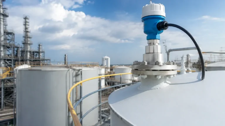
Tdr Radar Level Transmitter
TDR Radar Level Transmitter: Engineering Guide for Industrial Level Measurement
In the landscape of industrial process automation, achieving precise and reliable level measurement is a fundamental requirement for operational safety and efficiency. Among the various technologies available, the tdr radar level transmitter—often referred to as Guided Wave Radar (GWR)—has emerged as a preferred solution for challenging applications where traditional non-contact methods may struggle. This guide provides a technical overview of TDR technology, its measurement principles, selection criteria, and practical installation considerations for engineering professionals.
Understanding the TDR Measurement Principle
Time Domain Reflectometry (TDR) is a contact-based radar technology. Unlike non-contact Radar Level Meters that broadcast electromagnetic waves through the air, a TDR transmitter guides high-frequency, low-energy microwave pulses along a physical probe (waveguide).
The Physics of Reflection
When these pulses travel down the probe and encounter the surface of the process medium (liquid or solid), a portion of the pulse energy is reflected back to the transmitter electronics. This reflection occurs due to a sudden change in the dielectric constant ($ε_r$) between the upper medium (usually air or vapor) and the lower medium (the product being measured).
The transmitter measures the "time of flight"—the interval between the emission of the pulse and the reception of the echo. Since the speed of light in a vacuum/air is a known constant, the distance to the product surface is calculated using the formula:
Distance = (Speed of Light × Time of Flight) / 2
Once the distance is determined, the transmitter subtracts this value from the total tank height to provide an accurate level reading. Because the pulse is physically guided, the signal is less susceptible to attenuation caused by foam, dust, steam, or turbulent surfaces compared to open-air radar systems.
Key Components and Probe Variations
The performance of a tdr radar level transmitter is heavily dependent on the type of probe selected. The probe acts as the interface between the electronics and the process material. There are three primary configurations used in industrial engineering:
1. Single Rod/Cable Probes
These are the most versatile and common. They consist of a single stainless steel rod or flexible cable. They are ideal for viscous liquids or materials that may cause build-up, as they are the easiest to clean. However, they require a larger dielectric difference to produce a strong signal reflection.
2. Twin Rod/Cable Probes
Twin probes consist of two parallel conductors. This configuration creates a more concentrated electromagnetic field between the rods, making them suitable for liquids with lower dielectric constants. They are often used in long-range applications up to 20 meters, though they are more prone to bridging if the material is sticky.
3. Coaxial Probes
Coaxial probes function like a high-frequency cable, with a central rod inside an outer tube. This design offers the highest signal-to-noise ratio because the electromagnetic field is entirely contained within the tube. They are unaffected by internal tank obstructions or nozzles and are the best choice for very low dielectric liquids (down to $ε_r$ 1.4) and highly turbulent surfaces.
Technical Selection Criteria
Selecting the correct instrument requires a detailed analysis of the process environment. Engineers should consult the following table when evaluating probe types for specific media:
| Feature | Single Rod/Cable | Twin Rod/Cable | Coaxial Probe |
| :— | :— | :— | :— |
| Recommended Media | Viscous liquids, solids, slurries | Clean liquids, water-based | Low dielectric fuels, oils |
| Dielectric Constant (ε_r) | > 1.8 | > 1.4 | > 1.2 |
| Max Measurement Range | Up to 30m (cable) | Up to 20m | Up to 6m |
| Resistance to Coating | High | Moderate | Low |
| Turbulence Handling | Moderate | Good | Excellent |
| Foam Penetration | Good | Excellent | Excellent |
Dielectric Constant Considerations
The dielectric constant of the material is the most critical factor in TDR signal strength. Water has a high dielectric constant (~80), providing a very strong reflection. Conversely, hydrocarbons and oils often have low dielectric constants (2.0 to 5.0), requiring more sensitive electronics or coaxial probe designs to ensure a reliable return signal.
Interface Measurement Capabilities
One of the unique advantages of a tdr radar level transmitter is its ability to measure both the total level and the interface level between two immiscible liquids (e.g., oil over water).
When the microwave pulse hits the upper layer (oil), a portion of the signal reflects back (the first echo). The remaining energy continues through the low-dielectric upper layer and reflects off the high-dielectric lower layer (water), creating a second echo. This allows the transmitter to output two distinct measurements simultaneously, which is invaluable in separator tanks and chemical processing.

Installation Guidelines and Constraints
To ensure the accuracy of Radar Level Meters using TDR technology, specific installation parameters must be followed:
1. Dead Zones (Blocking Distances): Every TDR transmitter has an upper and lower dead zone. The upper dead zone is typically 100mm to 300mm from the process connection where measurements are not possible. The lower dead zone occurs at the very tip of the probe. Engineers must account for these when sizing the probe length.
2. Nozzle Dimensions: For single rod probes, the nozzle diameter and height can affect the signal. Ideally, the nozzle diameter should be as large as possible, and the probe should be centered. If the nozzle is very narrow and tall, a coaxial probe or a bypass pipe may be necessary.
3. Proximity to Walls: Probes should generally be installed at least 300mm away from the tank wall to prevent interference, especially in non-metallic tanks or tanks with internal ribs.
4. Obstructions: While TDR is more forgiving than non-contact radar, the probe should still be placed away from agitators, heating coils, and inlet flows to prevent mechanical damage or signal noise.
5. Solid Materials: When measuring solids (like grain or plastic pellets), the probe is subject to significant pull-down forces as the material settles. High-tensile strength cables and heavy-duty process connections are required to prevent the probe from being ripped out of the tank roof.
Limitations and Application Risks
While highly effective, TDR technology is not a universal solution. Engineers should be aware of the following limitations:
* Mechanical Stress: In tall silos containing heavy solids, the lateral force on a cable probe can exceed several tons. Structural calculations are required for these installations.
* Build-up and Bridging: While single rods handle coating well, extreme build-up that "bridges" the gap between a twin rod or the rod and tube of a coaxial probe will cause false high-level readings.
* Probe Length Limits: Rigid rod probes are typically limited to 6 meters due to shipping and installation constraints. For deeper tanks, flexible cable probes must be used, which require a weight at the bottom to keep them vertical.
Frequently Asked Questions (FAQ)
Q: Can TDR radar be used in vacuum applications?
A: Yes. Since TDR relies on electromagnetic waves rather than sound, it functions perfectly in a vacuum. However, the process seal must be rated for vacuum service to prevent leakage into the transmitter housing.
Q: How does temperature affect the measurement?
A: TDR is largely unaffected by temperature variations in the vapor space. However, extreme temperatures may slightly change the dielectric constant of some materials, which might require a minor calibration adjustment for the interface level.
Q: Is it possible to shorten a TDR probe in the field?
A: Most cable and rod probes can be cut to length in the field. After cutting, the transmitter software must be updated with the new probe length to maintain accuracy.
Q: Does the tank material matter?
A: For coaxial probes, the tank material is irrelevant. For single rod probes in plastic tanks, a metal flange or a ground plate is usually required at the process connection to provide a reference for the electromagnetic pulse.
Conclusion for International Procurement
When sourcing a tdr radar level transmitter for global projects, it is essential to confirm the necessary certifications (such as ATEX/IECEx for hazardous areas) and communication protocols (HART, Modbus, or Profibus). By understanding the dielectric properties of the medium and the mechanical constraints of the vessel, engineers can select a TDR solution that provides maintenance-free, high-precision level monitoring for years of service.