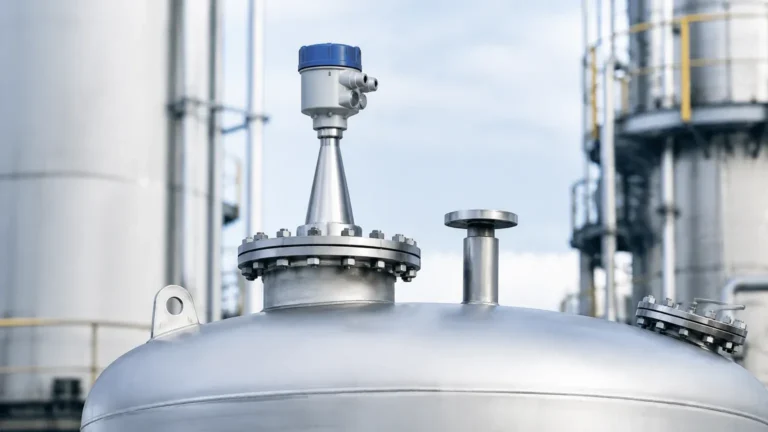
Radar Level Transmitter Wika
Radar Level Transmitter Wika: A Technical Engineering Guide to Radar Level Measurement
In the landscape of industrial process automation, accurate level measurement is critical for inventory management, process safety, and operational efficiency. Among the various technologies available, non-contact radar level measurement has emerged as a gold standard for challenging environments. A radar level transmitter, such as those within the Wika portfolio, utilizes electromagnetic waves to determine the distance to a product surface. This guide provides a comprehensive technical analysis of radar level measurement principles, selection criteria, and installation considerations for engineers and procurement professionals.
Understanding the Measurement Principles of Radar Level Transmitters
Radar level measurement operates on the principle of "Time of Flight" (ToF). The transmitter, mounted at the top of a vessel, emits a high-frequency signal toward the material surface. This signal reflects off the surface and returns to the sensor. By measuring the time interval between emission and reception, the device calculates the distance, which is then converted into a level or volume reading.
There are two primary methods used in radar level transmitters:
1. Pulse Radar (Time of Flight)
Pulse radar transmitters emit short microwave pulses. The device measures the time it takes for a single pulse to travel to the surface and back. This method is energy-efficient and suitable for many standard liquid applications. However, it may struggle with very low dielectric materials or turbulent surfaces where signal integrity is compromised.
2. Frequency Modulated Continuous Wave (FMCW)
FMCW technology, often found in high-end Radar Level Meters, emits a continuous signal with a constantly changing frequency. The distance is calculated based on the frequency difference between the emitted and received signals at any given moment. FMCW provides significantly higher accuracy and a better signal-to-noise ratio, making it the preferred choice for solids, powders, and liquids with low dielectric constants.
Technical Specifications of the Radar Level Transmitter Wika Range
When evaluating a radar level transmitter Wika model, such as the RLS-2000 or the Optiwave series (often integrated into Wika’s solution packages), several technical parameters define the instrument's performance. These instruments are designed to handle extreme process conditions, including high pressures and temperatures.
Frequency Bands
The frequency of the radar signal determines the beam angle and the instrument's ability to penetrate dust or steam:
* 6 GHz (C-Band): Best for applications with heavy foam or extreme turbulence, as the longer wavelength is less affected by surface disturbances.
* 26 GHz (K-Band): A versatile mid-range frequency suitable for most liquid tanks. It offers a balance between beam focusing and resistance to internal tank obstructions.
* 80 GHz (W-Band): The modern standard for precision. The high frequency allows for a very narrow beam angle (often less than 4°), which minimizes interference from tank walls, agitators, and heating coils. It is ideal for small vessels and tall, narrow silos.
Material Compatibility
Transmitters are typically constructed with wetted parts made from 316L stainless steel, Hastelloy, or plastics like PTFE and PEEK for corrosive environments. Ensuring the antenna material is compatible with the process media is essential for long-term reliability.
Selection Criteria for Industrial Level Measurement
Choosing the correct radar level transmitter requires a detailed analysis of the process environment. Engineers should use the following table as a preliminary selection framework:
| Feature | Liquid Storage | Chemical Reactors | Solids/Powders | Water/Wastewater |
| :— | :— | :— | :— | :— |
| Recommended Frequency | 26 GHz or 80 GHz | 80 GHz | 80 GHz (FMCW) | 26 GHz |
| Antenna Type | Horn or Lens | Flanged Lens | Drop Antenna | Encapsulated Horn |
| Accuracy | ±2 mm to ±5 mm | ±1 mm | ±5 mm to ±10 mm | ±2 mm |
| Dielectric Constant ($ε_r$) | > 1.4 | > 1.4 | > 1.1 | High (Water is ~80) |
| Pressure Range | Atmospheric | Up to 100 bar+ | Atmospheric | Atmospheric |
The Role of the Dielectric Constant ($ε_r$)
The dielectric constant of the media is perhaps the most critical factor. Radar waves reflect more strongly off materials with high dielectric constants (e.g., water, acids). For materials with low dielectric constants, such as hydrocarbons ($ε_r$ 1.9–2.5) or liquefied gases, a high-sensitivity FMCW transmitter or a guided wave radar (GWR) may be required to ensure a reliable return signal.
Installation Best Practices for Radar Level Sensors
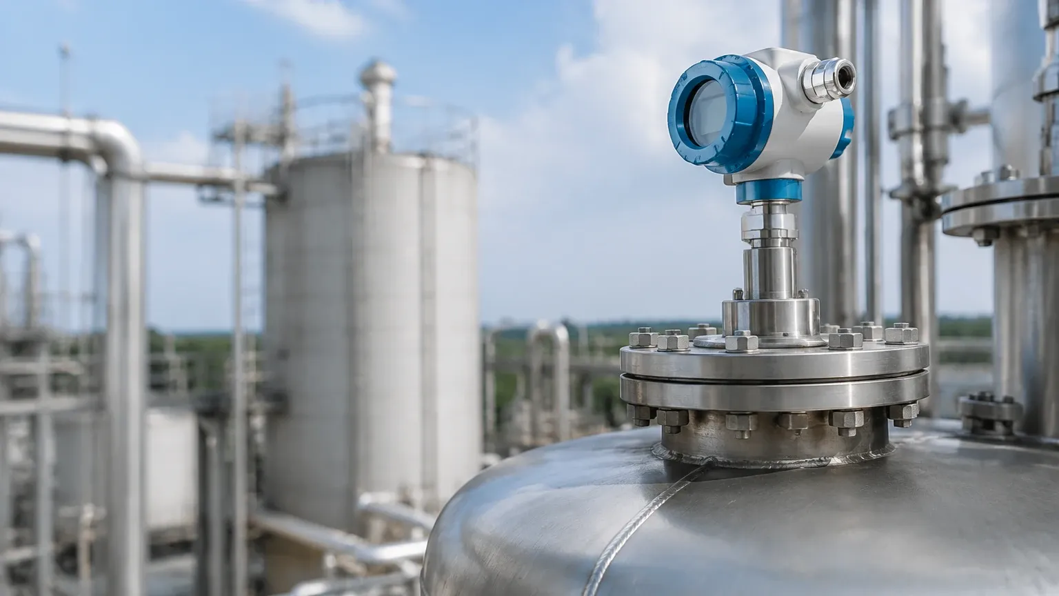
Proper installation is paramount to the performance of a radar level transmitter Wika or any similar high-precision instrument. Even the most advanced sensor will fail if the installation environment creates excessive noise or signal blockage.
1. Nozzle Geometry
The mounting nozzle should be as short as possible. If the nozzle is too long or narrow, the radar beam can reflect off the internal edges of the nozzle before it even enters the tank, creating a "ringing" effect that masks the true level signal. Ideally, the antenna should extend slightly below the bottom of the nozzle.
2. Avoiding Obstructions
The radar beam spreads as it travels. Engineers must calculate the beam diameter at the maximum measuring distance to ensure it does not hit tank walls, ladders, or agitator blades.
* Calculation Example: For a 26 GHz transmitter with a 10° beam angle, at a distance of 10 meters, the beam diameter is approximately 1.75 meters. Any internal structure within this radius will cause a false reflection.
3. Positioning and Orientation
* Off-Center Mounting: Never mount a radar transmitter in the exact center of a tank with a domed roof, as this can cause multiple reflections to converge at the sensor, leading to measurement errors.
* Parallelism: The sensor face must be parallel to the product surface. For solids, which form a conical heap, an adjustable flange (aiming kit) is often necessary to align the beam with the slope of the material.
Limitations and Application Challenges
While radar technology is robust, it is not a universal solution. Certain conditions can attenuate the signal or create false readings.
* Heavy Foam: Dense, thick foam can absorb radar signals entirely. In such cases, low-frequency (6 GHz) radar or contact-based methods like magnetic level gauges may be more effective.
* Dust and Condensation: While 80 GHz radar can penetrate moderate dust, extreme concentrations in grain silos or cement plants can cause signal scattering. Lens antennas with a flushing connection (air purge) are recommended to prevent buildup on the sensor face.
* Vacuum Conditions: Radar waves do not require a medium to travel, so they work perfectly in a vacuum. However, the mechanical seals of the transmitter must be rated for vacuum service to prevent air ingress or sensor damage.
Maintenance and Troubleshooting Guide
Modern radar level transmitters are largely maintenance-free due to the lack of moving parts. However, periodic verification is recommended in critical safety loops.
Common Issues and Solutions
1. Signal Loss (E014/E036 errors): Often caused by heavy buildup on the antenna or a sudden drop in the dielectric constant of the media. Cleaning the antenna or increasing the gain (sensitivity) settings can resolve this.
2. Fixed Value Output: If the transmitter stays at a specific percentage despite level changes, it is likely locked onto a false reflection (e.g., a tank internal). Performing a "False Signal Suppression" or "Empty Tank Mapping" allows the software to ignore these static echoes.
3. Fluctuating Readings: Usually caused by surface turbulence or agitator interference. Increasing the damping time (integration time) in the software settings can stabilize the output.
Frequently Asked Questions (FAQ)
Q: Can a radar level transmitter measure through a plastic tank wall?
A: Yes, if the tank is made of non-conductive plastic (like PE or PP) and is not reinforced with metal fibers, a radar signal can pass through the wall. This allows for "non-invasive" measurement where the sensor is mounted outside the tank.
Q: What is the difference between Guided Wave Radar (GWR) and Non-Contact Radar?
A: Non-contact radar sends waves through the air. GWR uses a physical probe (rod or cable) to guide the microwave signal. GWR is better for very low dielectric liquids and applications with heavy foam, while non-contact radar is preferred for corrosive or hygienic applications where touching the media is undesirable.
Q: How does temperature affect radar accuracy?
A: Unlike ultrasonic sensors, radar waves are electromagnetic and are not significantly affected by changes in air temperature, pressure, or gas composition. This makes radar much more accurate in fluctuating process conditions.
Conclusion
The implementation of a radar level transmitter Wika solution offers high-precision, non-contact measurement suitable for the most demanding industrial environments. By understanding the nuances of frequency selection, dielectric properties, and installation geometry, engineers can ensure long-term operational stability. For those seeking to upgrade their instrumentation, exploring the latest Radar Level Meters provides a pathway toward more digitized and reliable process control.
When selecting equipment, always verify the specific hazardous area certifications (ATEX, IECEx) and pressure ratings required for your facility to ensure compliance with local safety standards. Factual data and site-specific constraints should always dictate the final hardware configuration.