Magnetic Meters
Magnetic Meters
In industrial process control, the ability to monitor liquid levels with high reliability and visibility is paramount. Magnetic meters, specifically magnetic level gauges and their associated transmitters, have become a standard solution for challenging environments where glass gauges or electronic-only sensors may fail or present safety risks. These instruments leverage the fundamental laws of buoyancy and magnetism to provide a clear, real-time indication of fluid levels in tanks, pressure vessels, and boilers.
As a professional manufacturer, Welk provides a comprehensive suite of level measurement instruments, including radar, ultrasonic, and hydrostatic solutions. However, magnetic meters remain a cornerstone for applications involving high pressures, high temperatures, and hazardous chemicals. This guide serves as a practical engineering reference for selecting, installing, and maintaining magnetic level measurement systems across various industrial sectors.
Principles of Operation
To effectively implement magnetic meters in a facility, it is essential to understand the underlying physical principles: the Archimedes' Principle of buoyancy and the interaction of magnetic fields.
The Buoyancy Principle
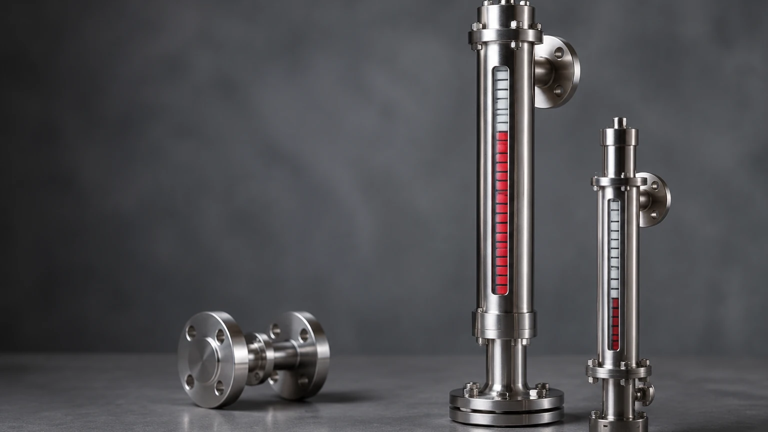
A magnetic level meter typically consists of a bypass chamber (a vertical pipe) connected to the side of a vessel. According to the principle of communicating vessels, the liquid level in the chamber matches the level in the main tank. Inside this chamber is a float specifically engineered to have a lower density than the process fluid. As the liquid level rises or falls, the float moves accordingly.
Magnetic Coupling
The float is equipped with a high-intensity permanent magnet assembly. Outside the chamber, a visual indicator—often consisting of a series of bi-color (e.g., red and white) magnetic flags or rollers—is mounted. As the float moves past these flags, the magnetic field causes them to rotate 180 degrees. Because the flags are bi-colored, the transition creates a distinct color change at the exact point of the liquid level.
This coupling is entirely mechanical and requires no external power for visual indication. For automation purposes, external sensors like reed switches or magnetostrictive transmitters can be clamped to the outside of the chamber to convert the float's position into a 4-20mA or digital signal. For more information on integrated measurement systems, you can visit the Main Page of our product catalog.
Key Components of Magnetic Meters
Understanding the construction of these instruments helps in evaluating their durability and suitability for specific process conditions.
1. The Chamber: Usually constructed from non-magnetic materials like 304 or 316L stainless steel, Hastelloy, or plastics like PVC/PP for corrosive environments. The chamber must withstand the process pressure and temperature.
2. The Float: This is the most critical component. It must be designed to match the specific gravity (SG) of the liquid. If the SG is too low, a standard float might sink; if it is too high, the float might sit too high in the liquid, leading to inaccuracies.
3. The Indicator: This provides the visual interface. High-quality indicators are hermetically sealed in glass or polycarbonate tubes to prevent moisture ingress or dust from interfering with flag rotation.
4. Process Connections: These are the flanges or threaded NPT/BSP connections that link the meter to the vessel. Common sizes range from DN15 to DN50 (1/2" to 2").
Selection Criteria for Industrial Applications
Choosing the right magnetic meter requires a detailed analysis of the process environment. Engineers should confirm the following parameters before procurement:
Specific Gravity (SG)
The float must be lighter than the liquid it displaces. Standard floats are often designed for an SG of 0.8 to 1.2. For liquefied gases or light hydrocarbons with an SG as low as 0.4, specialized titanium or thin-walled stainless steel floats are required.
Pressure and Temperature
Magnetic meters can handle extreme conditions, with some models rated for pressures up to 420 bar (approx. 6000 psi) and temperatures from -196°C to +450°C. However, at higher temperatures, the magnetic strength of the float can diminish (reaching the Curie point), so high-temperature magnets must be specified.
Material Compatibility
For acidic or alkaline solutions, the wetted parts (chamber and float) must be resistant to corrosion. PTFE (Polytetrafluoroethylene) lining is a common choice for aggressive chemicals where stainless steel is insufficient.
Selection Table for Magnetic Meters
| Feature | Standard Stainless Steel | PTFE Lined / Plastic | High-Pressure Models |
| :— | :— | :— | :— |
| Max Pressure | 40 bar (4.0 MPa) | 10-16 bar (1.0-1.6 MPa) | Up to 420 bar (42 MPa) |
| Max Temp | 250°C | 120°C (Plastic) / 200°C (Lined) | 450°C |
| Fluid Type | Water, Oil, Solvents | Acids, Bases, Bleach | High-pressure Steam, LPG |
| Visibility | Excellent | Excellent | Excellent |
| Power Req. | None (Visual) | None (Visual) | None (Visual) |
Installation Considerations
Proper installation is vital for the accuracy and longevity of magnetic meters. Failure to follow engineering best practices can lead to float jamming or indicator failure.
* Vertical Alignment: The chamber must be installed perfectly vertical. Even a slight tilt can cause the float to rub against the chamber walls, leading to friction and eventual sticking.
* Magnetic Interference: Keep the meter away from large motors, transformers, or high-voltage cables. External magnetic fields can interfere with the coupling between the float and the indicator flags.
* Vibration Dampening: In applications with high mechanical vibration (e.g., near large pumps), use support brackets to stabilize the chamber and prevent the indicator flags from flipping accidentally.
* Isolation Valves: Always install isolation valves between the tank and the meter. This allows for maintenance or cleaning without draining the entire vessel.
* Vent and Drain: Ensure the meter has a vent plug at the top and a drain valve at the bottom to facilitate commissioning and cleaning of sediment.
Limitations and Risks
While magnetic meters are robust, they are not universal solutions. Engineers should be aware of the following limitations:
1. Magnetic Particles: If the process fluid contains iron filings or magnetic scale, these particles will cling to the float's magnet. This increases the float's weight and can eventually jam it against the chamber wall. Magnetic traps or filters should be used in such cases.
2. High Viscosity: Extremely viscous liquids (like heavy crude or molasses) can impede the movement of the float. If the liquid cannot flow freely through the bypass, the meter will show a significant lag.
3. Coating and Scaling: If the fluid tends to crystallize or form a thick coating, the float may become stuck. Periodic flushing is required for these applications.
4. Initial Cost: Compared to simple sight glasses, magnetic meters have a higher initial capital expenditure, though this is usually offset by lower maintenance and higher safety ratings.
Integration with Control Systems
To move beyond simple visual monitoring, magnetic meters are often paired with electronic components. This transforms a manual gauge into a comprehensive "magnetic meter" system for industrial automation.
* Reed Switch Point Level: These are clamped to the chamber at specific heights (e.g., High-High, Low-Low). When the float magnet passes the switch, it triggers an alarm or stops a pump.
* Magnetostrictive Transmitters: These provide a continuous 4-20mA HART or Modbus signal. They offer high precision (up to ±1mm) and are mounted externally, meaning they never come into contact with the process fluid. This makes them much easier to maintain than invasive electronic sensors.
For technical assistance in choosing between visual gauges and integrated transmitters, engineers can Review product options and application support to find the configuration that best fits their site requirements.
Frequently Asked Questions (FAQs)
Q: Can magnetic meters be used for interface measurement (e.g., oil on water)?
A: Yes. By weighting the float to a specific density that is between the densities of the two liquids, the float will sink through the top layer and float on the bottom layer, accurately indicating the interface level.
Q: What is the maximum length for a magnetic level gauge?
A: While standard units are often up to 6 meters (approx. 20 feet), they can be manufactured in sections and joined with flanges for taller tanks. However, support brackets are mandatory for long spans.
Q: Do these meters require calibration?
A: The visual indicator does not require calibration as it is a direct physical relationship. However, if an external transmitter is used, it may require a one-time zero and span calibration during commissioning.
Q: How do I handle liquids that might freeze or solidify?
A: Magnetic meters can be equipped with steam jackets or electric heat tracing to maintain the fluid temperature within the chamber, ensuring the float remains mobile.
Conclusion
Magnetic meters represent a reliable, low-maintenance, and safe method for liquid level monitoring in the B2B sector. By eliminating the risks associated with fragile glass and providing a clear visual interface that works even during power outages, they serve as a critical safety and operational tool. When selecting a system, always prioritize the specific gravity of the fluid and the pressure/temperature ratings of the vessel to ensure a long-lasting installation. For more detailed specifications and engineering support, visit our Main Page.