Rheonik Coriolis
Rheonik Coriolis
In the field of industrial process control, the measurement of mass flow is a critical parameter for ensuring product quality, safety, and economic efficiency. Among the various technologies available, Coriolis mass flow meters are often regarded as the gold standard for accuracy and reliability. Rheonik Coriolis meters, specifically, have carved a niche in the market due to their unique engineering approach, particularly the "Omega" tube design. This guide provides a technical overview of the measurement principles, selection criteria, and installation requirements for these instruments, while exploring how they complement traditional level measurement systems.
The Fundamental Principle of Coriolis Mass Flow Measurement
To understand the performance of a Rheonik Coriolis meter, one must first grasp the Coriolis effect. The Coriolis force is an inertial force that acts on objects that are in motion within a frame of reference that rotates with respect to an inertial frame. In a flow meter, this principle is applied by vibrating a measuring tube (or tubes) through which the fluid flows.
The Physics of the Measurement
As the fluid moves through the vibrating tube, it is subjected to Coriolis acceleration. This results in a Coriolis force ($F_c$) described by the formula:
$$F_c = 2 \cdot m \cdot (v \times \omega)$$
Where:
* m is the mass of the fluid.
* v is the velocity of the fluid.
* ω is the angular velocity of the vibrating tube.
This force causes a slight distortion or "twisting" of the measuring tube. Sensors located at the inlet and outlet of the tube detect this distortion as a phase shift in the vibration cycle. This phase shift is directly proportional to the mass flow rate. Because the measurement is based on mass rather than volume, it is inherently independent of changes in fluid density, viscosity, temperature, and pressure, provided the sensor is correctly calibrated.
Simultaneous Density and Temperature Measurement
In addition to mass flow, Coriolis meters are capable of measuring fluid density and temperature. Density is determined by measuring the resonant frequency of the vibrating tubes; a denser fluid increases the mass of the system, thereby lowering the vibration frequency. Temperature is typically measured via an integrated RTD (Resistance Temperature Detector) to compensate for changes in the tube's elasticity (Young's Modulus) caused by thermal fluctuations.
The Rheonik Omega Tube Design: Engineering Advantages
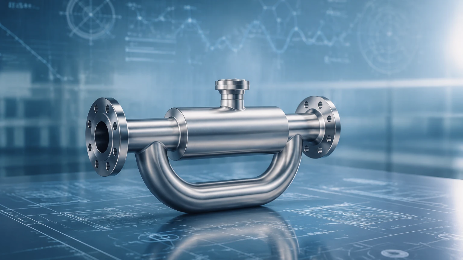
While many Coriolis meters utilize U-shaped or straight tubes, Rheonik is distinguished by its patented Omega-shaped tube design. This geometry offers several mechanical advantages that are particularly relevant in challenging industrial environments.
Torsion vs. Bending
The Omega shape allows the tubes to operate primarily in a torsional mode rather than a simple bending mode. This design concentrates the mechanical stress in specific areas designed to handle it, allowing for the use of thicker-walled tubes. Thicker walls provide greater resistance to high pressures (up to 1,400 bar or 20,300 psi) and corrosive wear, without sacrificing the sensitivity required for accurate mass flow measurement.
Decoupling from Pipe Vibration
The unique geometry of the Omega tube, combined with a robust mass bar structure, provides excellent decoupling from external pipe vibrations. In industrial plants, pumps and valves often create mechanical noise that can interfere with the high-frequency vibrations of a flow meter. The Rheonik design acts as a mechanical filter, ensuring that the phase shift detected is purely a result of the Coriolis force acting on the internal fluid.
Selection Criteria for Rheonik Coriolis Meters
Selecting the appropriate meter requires a thorough analysis of the process conditions. Rheonik categorizes its sensors (the RHM series) based on flow range, pressure rating, and material compatibility. The following table provides a generalized overview of common RHM series configurations used in industrial applications.
Table 1: Comparative Selection Overview for RHM Series
| Model Series | Typical Flow Range (kg/min) | Max Pressure (Standard) | Common Applications |
| :— | :— | :— | :— |
| RHM 015 to RHM 08 | 0.002 to 50 | Up to 1,000 bar | Chemical dosing, pilot plants, high-pressure gas filling. |
| RHM 10 to RHM 40 | 10 to 1,500 | Up to 400 bar | General process control, batching, loading/unloading. |
| RHM 60 to RHM 160 | 100 to 25,000 | Up to 350 bar | Custody transfer, large-scale marine bunkering, oil production. |
| RHM High Temp | Varies by size | Varies by size | Bitumen, molten sulfur, heat transfer oils (up to 400°C). |
Material Selection
The choice of wetted materials is critical for longevity. While 316L stainless steel is standard, many B2B applications involve aggressive media. Rheonik offers exotic alloys including:
* Hastelloy C22: For high resistance to oxidizing and reducing acids.
* Monel 400: Ideal for hydrofluoric acid and seawater applications.
* Tantalum: Used for extremely corrosive chemical processing where other alloys fail.
Installation Considerations and Best Practices
To achieve the specified accuracy (often ±0.1% or better for liquids), the installation must adhere to strict engineering guidelines. Coriolis meters are sensitive to the physical environment in which they are placed.
1. Orientation and Entrained Gas
For liquid applications, the meter should ideally be installed in a vertical line with the flow moving upward. This ensures the tubes remain full and prevents the accumulation of gas bubbles. If horizontal installation is necessary, the Omega tubes should point downward to prevent sediment build-up or upward to prevent gas trapping, depending on the fluid characteristics. Entrained gas (slug flow) is a primary cause of measurement error and "stalling" in Coriolis meters.
2. Mechanical Support and Stress
The meter must be installed without mechanical stress from the surrounding piping. Misaligned flanges can pull on the meter body, distorting the internal geometry and shifting the zero point. Supports should be placed on the piping immediately upstream and downstream of the meter, rather than supporting the meter body itself.
3. Zero Point Calibration
Every Coriolis meter must be "zeroed" after installation and under actual process conditions (temperature and pressure). This involves filling the meter with the process fluid, ensuring there is zero flow, and then running the zero-calibration routine on the transmitter. This accounts for any residual mechanical stress from the installation.
Limitations and Operating Constraints
Despite their versatility, Rheonik Coriolis meters are not a "one-size-fits-all" solution. Engineers must be aware of the following limitations:
* Pressure Drop: Because the fluid must travel through the curved Omega tubes, there is an inherent pressure drop. In high-viscosity applications (e.g., heavy crude oil or polymers), this drop can be significant and may require larger pump capacity or a larger meter size.
* Initial Capital Cost: Coriolis technology is generally more expensive than magnetic, vortex, or ultrasonic flow meters. The investment is typically justified only when mass flow accuracy, density measurement, or high-pressure capability is required.
* Size Constraints: While available in large sizes, the physical footprint and weight of a Coriolis meter for 12-inch (300 mm) piping are substantial, often requiring specialized structural supports.
Synergies Between Mass Flow and Level Measurement
In many B2B industrial environments, flow measurement and level measurement are used in tandem to provide a complete picture of process inventory. While a Coriolis meter measures the rate of material entering or leaving a vessel, level measurement instruments provide the absolute volume or mass currently stored.
For instance, in a chemical reactor, a Rheonik Coriolis meter might be used to precisely dose catalysts or reactants. Simultaneously, a radar or ultrasonic level sensor is used to monitor the total tank level to prevent overfilling. For comprehensive inventory management, engineers often combine high-precision mass flow data with direct level measurement sensors, such as those available on the Main Page.
Mass Balance Verification
Using both technologies allows for mass balance verification. If the mass flow meter indicates that 1,000 kg of fluid has entered a tank, but the hydrostatic level transmitter indicates an increase equivalent to only 900 kg, it alerts the operator to potential leaks, sensor drift, or unexpected changes in fluid density. This redundancy is essential in high-stakes industries like oil and gas or hazardous chemical manufacturing.
Frequently Asked Questions (FAQ)
Q: Can Rheonik Coriolis meters measure gas flow?
A: Yes, they are highly effective for gas measurement, particularly at high pressures where the gas density is higher. They are frequently used in hydrogen refueling stations and CNG (Compressed Natural Gas) dispensing.
Q: How does viscosity affect the accuracy?
A: Unlike volumetric flow meters, Coriolis meters are generally unaffected by viscosity changes. However, high viscosity will increase the pressure drop across the meter, which must be accounted for during the pump selection process.
Q: Is straight-run piping required before the meter?
A: Generally, no. Unlike turbine or vortex meters, Coriolis meters do not require long runs of straight pipe upstream or downstream. However, avoiding extreme turbulence or pulsations directly at the meter inlet is still a best practice.
Q: What is the typical lifespan of these instruments?
A: With no moving parts in the flow stream, the primary wear factor is erosion or corrosion. If the materials are correctly selected for the media, a Rheonik Coriolis meter can operate for 10 to 20 years with minimal maintenance.
Q: How do I handle "slug flow" or aeration?
A: Rheonik transmitters (such as the RHE series) include advanced signal processing and "gas bubble resilience" features to maintain measurement during brief periods of aeration. However, for continuous two-phase flow, specialized modeling or air eliminators are recommended.
By understanding the technical nuances of the Rheonik Coriolis system—from the torsion-based Omega tube design to the necessity of stress-free installation—engineers can ensure high-precision measurement in the most demanding process environments. When integrated with reliable level measurement technologies, these instruments form the backbone of modern industrial automation and inventory control.