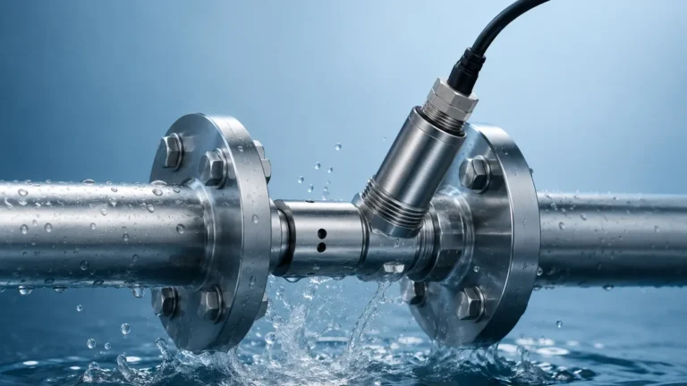
Clamp-on Ultrasonic Flow
Clamp-on Ultrasonic Flow
In modern industrial process control, the ability to measure fluid velocity without breaching the integrity of the piping system has become a critical requirement. Clamp-on ultrasonic flow measurement offers a non-invasive solution that eliminates the need for pipe cutting, process downtime, and the risk of leakage. This technology is increasingly utilized in sectors such as water treatment, chemical processing, and oil and gas, where maintaining a sealed system is paramount for safety and efficiency.
As a professional manufacturer of industrial measurement instruments, Welk provides advanced solutions that integrate seamlessly into automated environments. Understanding the underlying physics and application constraints of clamp-on ultrasonic flow meters is essential for engineers and plant managers tasked with selecting the most reliable instrumentation for their facilities.
Measurement Principles: Transit-Time vs. Doppler
Ultrasonic flow measurement relies on the transmission of high-frequency sound waves through a fluid. There are two primary methods used in industrial applications: Transit-Time and Doppler Effect. Selecting the correct principle depends entirely on the characteristics of the fluid being measured.
Transit-Time Ultrasonic Flow
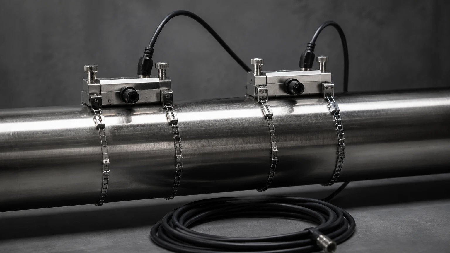
Transit-time technology is the most common method for measuring clean liquids. This principle utilizes two transducers that function as both transmitters and receivers. They are mounted on the outside of the pipe, either on opposite sides (Z-method) or the same side (V-method).
When the fluid is stationary, the time it takes for an ultrasonic pulse to travel from Transducer A to Transducer B is identical to the time from B to A. However, when the fluid is moving, the pulse traveling with the flow moves faster, while the pulse traveling against the flow is slowed down. The flow meter measures this minute time difference (nanoseconds) to calculate the flow velocity.
Key Formula Logic:
Flow velocity ($v$) is proportional to the time difference ($Δt$) divided by the product of the transit times. Once the velocity is determined and the internal pipe cross-section is known, the volumetric flow rate is calculated.
Doppler Effect Ultrasonic Flow
Doppler flow meters are designed for fluids containing suspended solids or entrained air bubbles. The transducers transmit a continuous high-frequency sound wave into the pipe. This sound reflects off the particles or bubbles moving with the fluid.
Because the reflectors are in motion, the frequency of the reflected wave is shifted (the Doppler effect). The frequency shift is directly proportional to the velocity of the particles. While less accurate than transit-time meters for clean water, Doppler meters are indispensable for slurries, aerated liquids, and wastewater applications where transit-time signals would be blocked or scattered.
Key Evaluation Criteria for Selection
When evaluating clamp-on ultrasonic flow solutions, several technical parameters must be confirmed to ensure measurement accuracy and long-term stability. Unlike inline meters, the pipe itself acts as part of the measuring circuit.
| Parameter | Requirement/Consideration |
| :— | :— |
| Pipe Material | Must be sonically conductive (e.g., Carbon Steel, Stainless Steel, PVC, Ductile Iron). |
| Pipe Lining | Linings like cement or bitumen can attenuate the signal; the lining must be well-bonded to the pipe wall. |
| Fluid Type | Clean liquids (Transit-time) vs. Slurries/Aerated liquids (Doppler). |
| Temperature Range | Standard transducers typically handle up to 80°C; high-temp versions reach 150°C or higher. |
| Pipe Diameter | Ranges typically from 15 mm to over 6,000 mm depending on transducer frequency. |
| Accuracy | Typically 0.5% to 2% of flow rate after proper calibration and installation. |
Installation Considerations and Best Practices
The performance of a clamp-on ultrasonic flow meter is heavily dependent on the quality of the installation. Because the sensors are not in direct contact with the fluid, the signal must pass through the pipe wall and any internal lining before reaching the medium.
1. Straight Pipe Requirements
To ensure a stable flow profile, the sensors must be installed on a straight section of pipe. The standard engineering guideline is the "10D and 5D rule":
* Upstream: At least 10 times the pipe diameter (10D) of straight pipe after any elbows, valves, or pumps.
* Downstream: At least 5 times the pipe diameter (5D) of straight pipe before the next fitting.
If the flow is highly turbulent due to a double elbow or a partially closed valve, upstream requirements may increase to 20D or 40D.
2. Surface Preparation
The exterior of the pipe must be cleaned of all loose paint, rust, and scale. A smooth, bare metal or plastic surface is required to allow the ultrasonic signal to penetrate the pipe wall. Once cleaned, a coupling agent (ultrasonic grease or gel) is applied to the face of the transducers to eliminate air gaps between the sensor and the pipe.
3. Transducer Mounting Orientations
* V-Method: The signal bounces once off the opposite pipe wall. This is the standard for pipes ranging from 25 mm to 400 mm.
* Z-Method: The signal travels directly across the pipe. This is used for large-diameter pipes or where the fluid has higher attenuation.
* W-Method: Used for very small pipes (typically under 50 mm) where the signal bounces multiple times to increase the transit distance and improve resolution.
Limitations and Technical Challenges
While clamp-on technology offers significant advantages, it is not a universal solution. Engineers must be aware of specific limitations that can compromise data integrity.
* Pipe Wall Condition: Excessive internal corrosion or scaling can scatter the ultrasonic signal. If the pipe is heavily pitted, the signal may not reach the fluid, resulting in a "Signal Lost" error.
* Multiphase Flow: Transit-time meters generally fail if the volume of suspended solids or bubbles exceeds 2% to 5%. In these instances, a Doppler-based system or an alternative technology like a magnetic flow meter may be required.
* Wall Thickness Uncertainty: The flow meter calculates velocity based on the internal diameter. If the actual pipe wall thickness differs from the nominal values programmed into the meter, the resulting flow rate calculation will be inaccurate. Using an ultrasonic thickness gauge to verify the pipe wall before installation is highly recommended.
* Extreme Temperatures: Very high or low temperatures can affect the speed of sound in the pipe material and the coupling gel. Specialized mounting hardware and high-temperature couplants are necessary for steam condensate or cryogenic applications.
Practical Selection Table for Industrial Applications
Choosing the right configuration involves balancing the fluid properties with the mechanical constraints of the site.
| Application | Recommended Technology | Primary Benefit |
| :— | :— | :— |
| Potable Water Distribution | Transit-Time (Fixed) | High accuracy, no contamination risk. |
| Chemical Dosing | Transit-Time (Small Pipe) | Resistance to corrosive media. |
| Wastewater/Sewage | Doppler | Handles high solids content. |
| HVAC Cooling Loops | Transit-Time (Portable) | Easy auditing of multiple lines. |
| Crude Oil Pipelines | Transit-Time (High Power) | Non-invasive measurement of viscous fluids. |
Frequently Asked Questions (FAQs)
Q: Can clamp-on meters measure flow in partially filled pipes?
No. Standard ultrasonic flow meters require a full pipe to ensure the sound waves have a continuous medium to travel through. For partially filled pipes, specialized area-velocity sensors or flumes are required.
Q: How often does the coupling agent need to be replaced?
For permanent installations, high-quality silicone-based couplants can last several years. However, in outdoor environments or high-vibration areas, it is best practice to inspect the signal strength annually and re-apply couplant if the signal has degraded.
Q: Does the pipe material affect the accuracy?
Yes. The meter must be programmed with the correct sound velocity for the specific pipe material. Materials like plastic (PVC/HDPE) have different acoustic properties than metals (Steel/Copper). Accuracy is maintained as long as the material properties are correctly entered.
Q: Can it measure flow in both directions?
Yes, transit-time ultrasonic meters are inherently bi-directional. They can distinguish between forward and reverse flow based on which transducer receives the pulse first.
Conclusion
Clamp-on ultrasonic flow measurement is a versatile and cost-effective tool for modern industrial automation. By eliminating the need for process interruption and providing a high degree of portability, it serves as an essential technology for both permanent monitoring and temporary flow audits. When integrated with other process instruments, such as those found on the Welk Main Page, these meters contribute to a comprehensive understanding of plant efficiency and resource management.
For successful implementation, engineers must prioritize proper site selection, meticulous surface preparation, and a clear understanding of the fluid's acoustic properties. When these factors are addressed, clamp-on ultrasonic flow meters provide a reliable, maintenance-free solution for the most demanding industrial environments.