Continuous Water Quality Monitoring Equipment
Continuous Water Quality Monitoring Equipment
In modern industrial processes, the transition from manual grab-sampling to automated data acquisition has become a standard for operational efficiency. Continuous water quality monitoring equipment refers to an integrated system of sensors, transmitters, and data controllers designed to provide real-time analysis of physical and chemical water parameters. These systems are critical in sectors ranging from municipal wastewater treatment and chemical manufacturing to oil and gas production, where maintaining specific water standards is essential for both regulatory compliance and equipment longevity.
Reliable monitoring ensures that process deviations are detected immediately, preventing environmental discharge violations and protecting downstream assets. To build an effective monitoring station, engineers must integrate various sensing technologies—including pH, conductivity, dissolved oxygen, and turbidity—alongside precise level measurement instruments to provide context for the analytical data. By understanding the underlying physics of these sensors and the importance of their physical placement, facility managers can optimize their water treatment cycles and reduce chemical consumption.
Measurement Principles of Water Quality Sensors
Before selecting continuous water quality monitoring equipment, it is necessary to understand the scientific principles that govern sensor performance. Each parameter requires a specific physical or electrochemical approach to ensure accuracy in varying process conditions.
Electrochemical Sensors (pH and ORP)
Most continuous pH monitoring is based on the potentiometric principle. A pH sensor typically consists of a glass electrode and a reference electrode. When immersed in water, a voltage (potential) is generated across the glass membrane that is proportional to the hydrogen ion activity. This relationship is defined by the Nernst Equation. Oxidation-Reduction Potential (ORP) sensors function similarly but use a noble metal electrode (usually platinum or gold) to measure the electron-donating or electron-accepting capacity of the solution, which is vital for monitoring disinfection processes like chlorination or ozone treatment.
Amperometric and Optical Dissolved Oxygen (DO)
Dissolved oxygen is measured using either amperometric (clark cells) or optical (luminescence-based) technology. Amperometric sensors rely on the diffusion of oxygen through a membrane to a cathode, creating a current proportional to the oxygen concentration. However, optical sensors are increasingly preferred in industrial B2B applications because they do not require a minimum flow rate and are less susceptible to fouling. Optical DO sensors measure the phase shift of blue light reflected off a sensing cap, where the presence of oxygen "quenches" the luminescence.
Conductivity and Total Dissolved Solids (TDS)
Conductivity measurement determines the water's ability to pass an electrical current, which correlates to the concentration of dissolved ionic species. There are two primary methods:
1. Contacting Conductivity: Uses two or four electrodes in direct contact with the fluid. This is highly accurate for pure water (low conductivity) applications like boiler feed water.
2. Inductive (Toroidal) Conductivity: Uses two internal coils to induce a current in the fluid. Since there are no exposed electrodes, this method is ideal for high-conductivity liquids or fluids that would coat or corrode standard electrodes, such as brine or wastewater.
Integration with Level Measurement Technologies
Continuous water quality monitoring equipment does not operate in a vacuum. To gain a complete picture of a water system, analytical data must be paired with physical volume and flow data. For instance, knowing the concentration of a pollutant is only half the requirement; an engineer must also know the total volume of the tank or the flow rate of the effluent to calculate the total mass loading.
Level measurement instruments, such as those found on the Main Page of industrial instrumentation providers, play a supportive yet critical role. In a typical wastewater treatment plant, radar level meters or ultrasonic level sensors are used to monitor the height of the water in aeration tanks or clarifiers. This data is fed into the same PLC (Programmable Logic Controller) as the water quality data.
If a pH sensor detects an acidic spike, the system uses the level data to determine how much neutralizing agent (like lime or caustic soda) is required based on the current volume of the tank. Without accurate level measurement, chemical dosing becomes a matter of guesswork, leading to either insufficient treatment or expensive chemical waste. Furthermore, hydrostatic level transmitters are often used in deep wells or reservoirs to ensure that water quality sensors remain submerged at the correct depth, preventing dry-run damage to sensitive membranes.
Practical Selection Criteria for Industrial Applications
Selecting the right continuous water quality monitoring equipment requires a balance between accuracy, durability, and maintenance requirements. The following table provides a comparison of common sensor types used in industrial water treatment:
| Parameter | Preferred Technology | Typical Range | Common Application |
| :— | :— | :— | :— |
| pH | Potentiometric (Glass) | 0–14 pH | Neutralization, Effluent Monitoring |
| Conductivity | Toroidal (Inductive) | 0–2,000 mS/cm | Chemical Concentration, Brine |
| Dissolved Oxygen | Optical (RDO) | 0–20 mg/L | Aeration Tanks, Aquaculture |
| Turbidity | Nephelometric (90°) | 0–4,000 NTU | Filter Monitoring, Raw Water |
| Free Chlorine | Amperometric | 0–20 ppm | Drinking Water, Cooling Towers |
Evaluation Factors
1. Response Time (T90): In fast-moving processes, such as chemical dosing in a pipe, a sensor must reach 90% of its final value quickly to prevent overshooting the setpoint.
2. Temperature Compensation: Water quality parameters are highly temperature-dependent. Ensure the equipment includes integrated PT100 or PT1000 temperature sensors for automatic compensation.
3. Housing Materials: In corrosive environments (e.g., seawater or acidic waste), sensors should be housed in PVDF (polyvinylidene fluoride) or 316L stainless steel rather than standard PVC.
4. Signal Output: Modern B2B systems should support 4-20mA HART, RS485 Modbus, or Profibus for seamless integration into SCADA systems.
Installation and Maintenance Considerations
The longevity of continuous water quality monitoring equipment is largely determined by the quality of the installation. Even the most expensive sensor will fail or provide false readings if placed incorrectly.
Sensor Placement
Sensors should be installed in areas of representative flow. Avoid "dead zones" where water stagnates, as this will lead to lagged readings. Conversely, avoid areas of extreme turbulence or air entrainment (bubbles), as bubbles can interfere with optical turbidity and DO sensors. In tanks, sensors should be positioned away from the walls to avoid interference but close enough to a walkway for safe maintenance access.
Mounting Methods
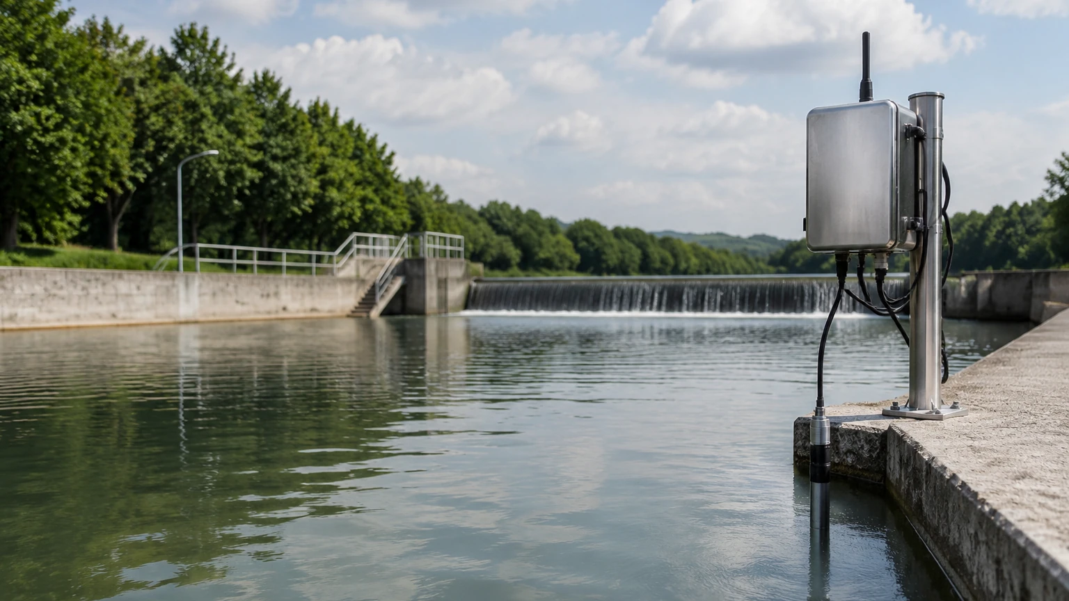
* Immersion Mounting: Sensors are attached to a pole or bracket and submerged directly into a tank or open channel. This is common in wastewater treatment.
* Flow-Through Cells: A small portion of the process water is diverted through a bypass line into a small chamber containing the sensors. This allows for easier calibration and cleaning without stopping the main process.
* In-Line Mounting: Sensors are mounted directly into a pressurized pipe using a retractable assembly. This allows the sensor to be removed for maintenance without depressurizing the line.
Maintenance and Calibration
Continuous monitoring does not mean "maintenance-free." Sensors require periodic cleaning to remove biofouling, mineral scaling, or oil coatings. Automated cleaning systems, such as compressed air blasts or mechanical wipers, can significantly extend the interval between manual cleanings. Calibration should be performed using NIST-traceable buffer solutions on a schedule determined by the drift characteristics of the specific sensor and the harshness of the process.
Common Risks and Limitations
Engineers must be aware of the inherent limitations of continuous water quality monitoring equipment to avoid data misinterpretation.
1. Biofouling: In warm, nutrient-rich water, algae and bacteria can grow on sensor surfaces within days. This creates a micro-environment that does not represent the bulk fluid, leading to significant errors in pH and DO readings.
2. Chemical Interference: Certain ions can interfere with ion-selective electrodes (ISE). For example, high levels of chloride can interfere with some nitrate sensors. Always check the chemical compatibility of the sensor with the full process fluid composition.
3. Electromagnetic Interference (EMI): Water quality sensors produce very low-voltage signals that are easily disrupted by nearby high-voltage cables or variable frequency drives (VFDs). Proper shielding and grounding of sensor cables are mandatory.
4. Pressure Limits: Most standard water quality sensors are rated for low-pressure applications (typically below 6 bar or 87 psi). High-pressure applications require specialized housings and reinforced membranes.
Frequently Asked Questions (FAQs)
Q: How often should I calibrate my continuous pH sensor?
A: This depends on the process. In stable, clean water, once a month may suffice. In harsh chemical processes or wastewater, weekly calibration is often necessary to account for electrode aging and drift.
Q: Can I use one transmitter for multiple parameters?
A: Yes, many modern multi-parameter controllers can accept inputs from 2 to 8 different sensors (e.g., pH, DO, and Conductivity) simultaneously, reducing installation costs and simplifying data management.
Q: What is the difference between NTU and FNU in turbidity measurement?
A: NTU (Nephelometric Turbidity Units) typically refers to measurements made using a white light source (EPA method), while FNU (Formazin Nephelometric Units) refers to measurements made using an infrared light source (ISO 7027 method). Infrared is generally better for colored waters as it reduces interference from dissolved organics.
Q: Do I need a specific flow rate for my sensors?
A: Amperometric DO and chlorine sensors require a minimum flow (usually around 0.1 to 0.5 m/s) to ensure a fresh supply of ions reaches the membrane. Optical sensors and conductivity sensors generally do not have a minimum flow requirement.
Conclusion
Implementing continuous water quality monitoring equipment is a strategic investment that enhances process control and environmental stewardship. By selecting the appropriate measurement principle—whether electrochemical, optical, or inductive—and integrating these analytical tools with robust level measurement systems, industrial operators can achieve a high degree of automation. Success in these applications relies on a rigorous approach to sensor selection, a commitment to proper installation, and a proactive maintenance schedule to combat the challenges of fouling and interference. As industry standards for water reuse and discharge tighten, the role of real-time data will only become more central to sustainable industrial operations.
Download Continuous Water Quality Monitoring Equipment as a PDF