Safety Instrumented Systems
Safety Instrumented Systems
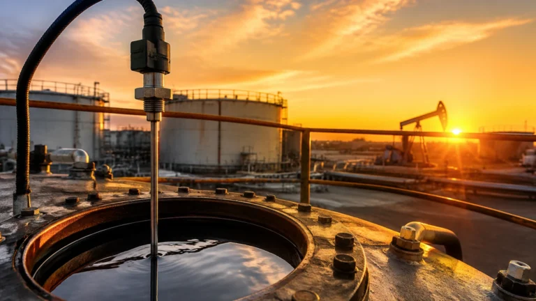
In the modern industrial landscape, process safety is not merely a regulatory requirement but a fundamental pillar of operational integrity. Among the various layers of protection employed in chemical processing, oil and gas refining, and water treatment, safety instrumented systems (SIS) stand as the critical final automated defense against catastrophic events. These systems are specifically designed to take a process to a safe state when predetermined conditions are violated, such as an overfill in a hazardous chemical tank or a dry-run condition in a high-pressure boiler.
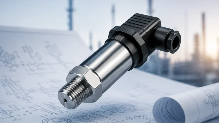
For engineers and plant managers, the effectiveness of an SIS is heavily dependent on the reliability of the field instrumentation. Level measurement, in particular, serves as a primary input for many safety instrumented functions (SIF). Understanding the interplay between level sensing technologies and SIS architecture is essential for achieving the required Safety Integrity Level (SIL) and ensuring long-term plant safety.
The Role of Level Measurement in Safety Instrumented Systems
A safety instrumented system is composed of three distinct elements: sensors, logic solvers, and final control elements (such as valves or pumps). The sensor’s role is to monitor process variables—like liquid level—and provide accurate data to the logic solver. If the level exceeds or falls below safety limits, the logic solver triggers the final control element to mitigate the risk.
In level measurement, the SIS typically addresses two primary risks:
1. Overfill Protection: Preventing a vessel from overflowing, which could lead to environmental contamination, fire, or explosions.
2. Low-Level Protection: Preventing pumps from cavitation or ensuring that heating elements remain submerged to avoid equipment damage or thermal runaway.
To ensure these systems perform as expected, they must adhere to international standards such as IEC 61508 (for manufacturers) and IEC 61511 (for process industry end-users). These standards define the safety lifecycle and the performance metrics required for instrumentation used in safety-critical applications.
Measurement Principles and Their SIS Suitability
Before selecting a level transmitter for an SIS, it is vital to understand the underlying measurement principles. Each technology has unique strengths and failure modes that impact its reliability within a safety loop.
Radar Level Measurement (GWR and Non-Contact)
Radar technology, including Guided Wave Radar (GWR) and non-contact (Free-Space) radar, is widely regarded as the gold standard for SIS level applications. Radar instruments emit electromagnetic pulses that reflect off the surface of the medium. The time-of-flight (ToF) is measured to determine the distance.
* Why for SIS: Radar is largely unaffected by changes in pressure, temperature, or vapor space composition. Since it does not rely on the physical properties of the fluid (like density or conductivity), it offers high diagnostic coverage. Non-contact radar is particularly valuable for corrosive or high-temperature media where sensor degradation is a risk.
Ultrasonic Level Sensors
Ultrasonic sensors function by emitting high-frequency sound waves. The sensor measures the time it takes for the echo to return from the liquid surface.
* Why for SIS: These are cost-effective solutions for water treatment and stable liquid storage. However, their use in SIS is often limited to non-volatile liquids, as heavy vapors or foam can attenuate the sound signal, leading to a "loss of echo"—a dangerous condition if not properly handled by the logic solver.
Hydrostatic Level Transmitters
Hydrostatic measurement determines level by sensing the pressure exerted by the liquid column ($P = \rho gh$).
* Why for SIS: This is a robust, well-understood technology with few moving parts. However, for safety loops, engineers must account for changes in liquid density ($\rho$). If the density changes due to temperature fluctuations or batch variations, the level reading will be inaccurate, potentially compromising the safety function.
Magnetic Level Gauges and Switches
Magnetic level gauges use a float containing a magnet that moves with the liquid level, coupled with an external indicator or switch.
* Why for SIS: They provide a clear visual indication independent of power, which is useful for manual verification. When equipped with reed switches or transmitters, they can be integrated into an SIS. Their mechanical nature makes them susceptible to "stuck float" scenarios, which requires specific diagnostic considerations.
Understanding Safety Integrity Levels (SIL)
The performance of an SIS is categorized by its Safety Integrity Level (SIL), ranging from SIL 1 (lowest) to SIL 4 (highest). Most industrial level applications require SIL 2 or SIL 3.
Achieving a specific SIL depends on two factors: the Probability of Failure on Demand (PFD) and the Safe Failure Fraction (SFF).
* PFD: This is the likelihood that the system will fail to perform its function when needed. For a SIL 2 system, the PFD must be between 0.01 and 0.001.
* SFF: This represents the percentage of possible failures that are either "safe" or "detected dangerous." High SFF is achieved through advanced internal diagnostics within the level transmitter.
When designing a safety loop, it is common to use redundant sensors to lower the PFD. For example, a 1oo2 (one-out-of-two) configuration means that if either of the two sensors detects a high level, the safety action is triggered. This increases safety but may increase the rate of false trips. A 2oo3 configuration is often used to balance safety with high process availability.
Selection Criteria for SIS Level Instrumentation
Choosing the right instrument requires a balance of technical capability and application-specific constraints. The following table provides a comparison of common technologies used in safety instrumented systems.
| Technology | SIS Suitability | Primary Advantage | Primary Limitation |
| :— | :— | :— | :— |
| Non-Contact Radar | High (SIL 2/3) | No contact with media; unaffected by density. | Higher initial cost; sensitive to heavy foam. |
| Guided Wave Radar | High (SIL 2/3) | Stronger signal in turbulence; works in low dielectric. | Probe can be damaged by mechanical stress or buildup. |
| Ultrasonic | Medium (SIL 1/2) | Low cost; easy installation. | Limited by vapor, foam, and vacuum conditions. |
| Hydrostatic | Medium (SIL 1/2) | Simple and reliable for stable liquids. | Density changes cause measurement errors. |
| Magnetic Gauge | Medium (SIL 1/2) | Visual backup; no power required for local display. | Moving parts can stick; magnetic particles interfere. |
For a detailed analysis of specific hardware and to Review product options and application support, engineers should visit our Main Page to find instruments with the necessary safety certifications.
Installation and Engineering Best Practices
Even the most advanced SIL-rated transmitter will fail to provide safety if installed incorrectly. Engineering teams must follow strict guidelines during the design and installation phases.
1. Redundancy and Diversity: To mitigate common-cause failures (where both sensors fail for the same reason, such as a shared process connection clogging), use diverse technologies. For instance, pairing a radar transmitter with a magnetic level switch provides a high degree of safety because they rely on different physical principles.
2. Standoff Pipes and Nozzles: Ensure that nozzles do not interfere with the signal path of radar or ultrasonic sensors. For non-contact radar, the beam angle must be clear of internal obstructions like ladders or agitators.
3. Environmental Protection: Level instruments in an SIS must be capable of withstanding extreme conditions. This includes NEMA 4X or IP66/67 ratings for moisture protection and surge protection for lightning strikes.
4. Separation of Functions: A fundamental rule of IEC 61511 is the separation of the Basic Process Control System (BPCS) and the SIS. You should not use the same transmitter for both day-to-day tank gauging and safety overfill protection unless specific, rigorous criteria are met.

Maintenance and Proof Testing
A critical component of maintaining the SIL rating of a system is the "Proof Test." Unlike standard calibration, a proof test is a periodic test performed to detect any failures in a safety instrumented system that are not detected by diagnostics.
* Full Proof Test: This involves physically changing the level in the tank to ensure the sensor detects the trip point and the final element (valve) closes.
* Partial Proof Test: In many modern radar units, internal software can simulate a high-level condition to test the electronics and logic solver without needing to fill the tank, though this does not test the physical coupling to the process.
Documentation of these tests is mandatory for compliance. If a proof test is missed, the SIL rating of the loop is technically void until the test is completed and recorded.
Common Risks and Limitations
While safety instrumented systems significantly reduce risk, they are not infallible. Engineers must remain aware of specific limitations:
* Systematic Failures: These are failures related to design, software bugs, or human error (e.g., incorrect programming of the trip point). These cannot be reduced by redundancy alone.
* Build-up and Fouling: In viscous or crystallizing media, material can build up on probes or diaphragms. While diagnostics may detect a "blocked" sensor, the safety function is still compromised until cleaned.
* Vapor Space Dynamics: In high-pressure applications, the dielectric constant of the vapor space can change, slightly affecting the speed of electromagnetic waves in radar systems. While usually negligible, in high-accuracy safety loops, this must be compensated for.
Frequently Asked Questions (FAQ)
Q: Can I use a standard level transmitter in an SIS?
A: No. Only instruments that have been certified by a third party (like exida or TÜV) or have a proven-in-use justification according to IEC 61511 should be used in an SIS.
Q: What is the difference between a safety trip and a process alarm?
A: A process alarm notifies an operator to take action. A safety trip (part of the SIS) is fully automated and takes action without human intervention to prevent an incident.
Q: How often should I perform proof testing on my level sensors?
A: The frequency is determined during the Safety Requirement Specification (SRS) phase and depends on the required PFD for your specific SIL target. Common intervals are 12, 24, or 36 months.
Q: Is non-contact radar better than guided wave radar for safety?
A: Not necessarily. Non-contact radar is better for corrosive or dirty media, while guided wave radar is often better for low-dielectric liquids or applications with heavy surface turbulence. Both can be SIL 2/3 certified.
Conclusion
Implementing safety instrumented systems is a complex but necessary endeavor for modern industrial operations. By selecting the appropriate level measurement technology—whether it be radar, ultrasonic, or hydrostatic—and adhering to the rigorous standards of the safety lifecycle, organizations can protect their personnel, the environment, and their assets. Always ensure that the selected instruments are properly rated for the required SIL and that installation follows best engineering practices to ensure the system performs when it matters most.