Wet Differential Pressure Transducer
Wet Differential Pressure Transducer
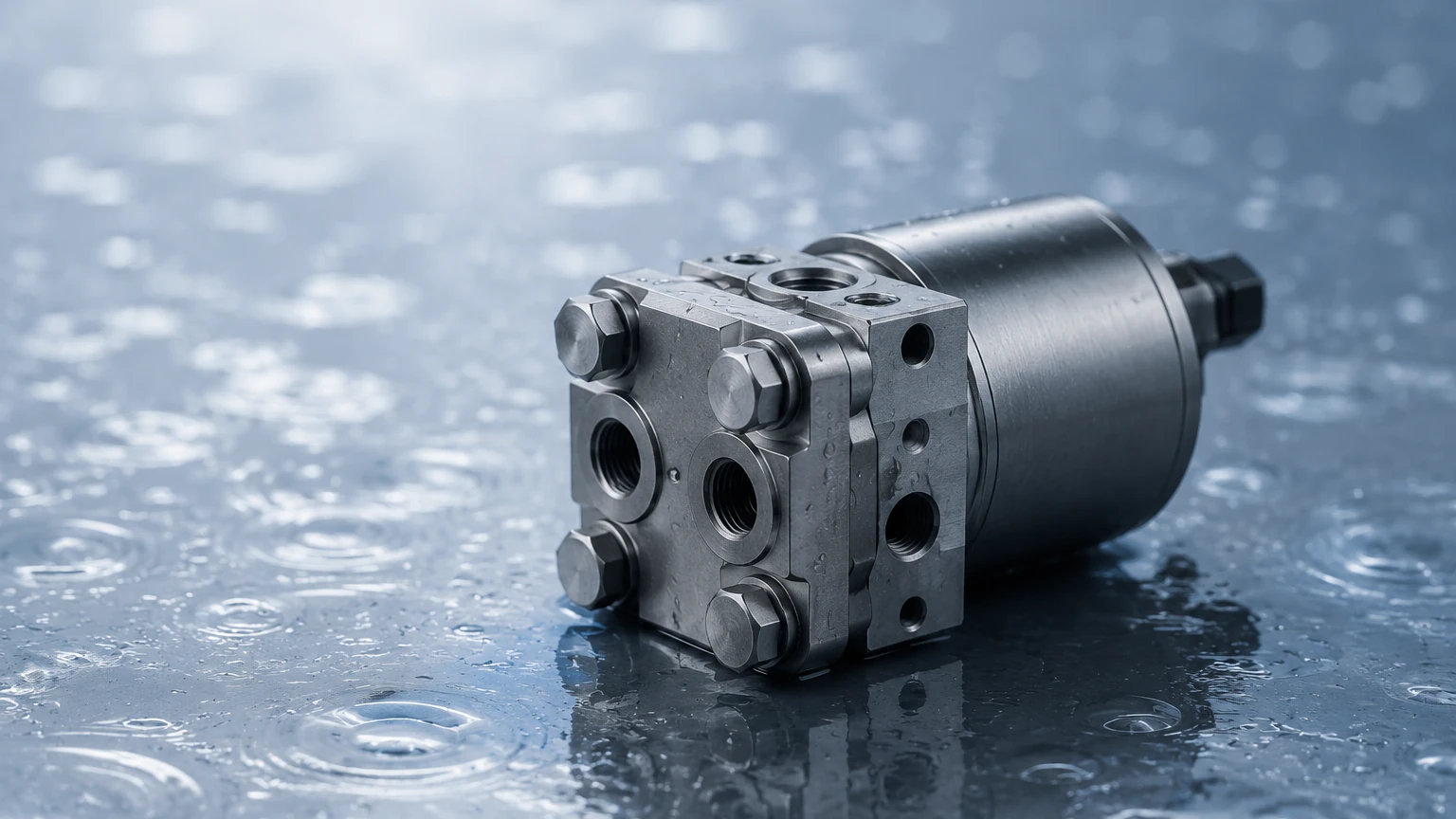
In the landscape of industrial process control, the wet differential pressure transducer stands as a foundational instrument for monitoring fluid levels, flow rates, and filter performance. Unlike standard pressure sensors that measure force relative to atmospheric pressure or a vacuum, a differential pressure (DP) transducer calculates the difference between two distinct pressure points. When both of these points are exposed to liquids—often corrosive, viscous, or under high static pressure—the device is classified as a "wet/wet" or simply a wet differential pressure transducer.
For engineers and plant managers, selecting the correct transducer requires a deep understanding of hydraulic principles, material compatibility, and the specific nuances of the application environment. This guide provides a technical overview of how these instruments function, their primary industrial applications, and the critical factors involved in their selection and installation.
Measurement Principles of Differential Pressure
The fundamental operation of a wet differential pressure transducer relies on a sensing element, typically a flexible diaphragm, positioned between two pressure chambers: the High Side (H) and the Low Side (L). The net force exerted on the diaphragm is proportional to the difference in pressure between these two chambers.
Hydrostatic Level Measurement
In liquid level applications, the transducer utilizes the principle of hydrostatic head pressure. For an atmospheric (open) tank, a single-ended pressure sensor is often sufficient. However, in pressurized (closed) vessels, the vapor space above the liquid exerts pressure on the surface. To measure only the liquid level, the transducer must subtract the vessel's internal pressure from the total pressure at the bottom.
The wet differential pressure transducer achieves this by connecting the high-side port to the bottom of the tank and the low-side port to the vapor space at the top. The resulting calculation is defined by the formula:
**ΔP = ρ * g * h**
Where:
* ΔP is the differential pressure.
* ρ (Rho) is the density of the liquid.
* g is the gravitational constant.
* h is the height of the liquid column.
Flow Measurement via Primary Elements
When used for flow measurement, the transducer is paired with a primary flow element, such as an orifice plate, Venturi tube, or Pitot tube. These elements create a localized restriction in the pipe, causing a pressure drop. According to Bernoulli’s principle, the square root of this differential pressure is proportional to the flow velocity. Because the media in these pipes is liquid, a wet differential pressure transducer is required to ensure the internal components are not damaged by the process fluid.
Key Components and Construction
To be classified as "wet," the transducer must be engineered to handle liquid contact on both sensing ports. This necessitates specific construction features:
1. Isolation Diaphragms: These are the thin, metallic membranes (often 316L Stainless Steel, Hastelloy C, or Tantalum) that come into direct contact with the process fluid. They protect the sensitive internal electronics from corrosion and contamination.
2. Fill Fluid: A non-compressible fluid, such as silicone oil or fluorinated oil, fills the internal cavity between the isolation diaphragm and the actual sensing chip (capacitive, piezoresistive, or silicon-on-sapphire). This fluid transmits the pressure force accurately while providing electrical insulation.
3. Process Connections: These are the mechanical interfaces (typically NPT threads or flanges) that allow the device to be integrated into the piping system.
Technical Selection Criteria
Choosing the right wet differential pressure transducer involves more than just matching a pressure range. Engineers must evaluate the following parameters to ensure long-term reliability and accuracy.
Selection Evaluation Table
| Parameter | Consideration | Impact on Application |
| :— | :— | :— |
| Differential Pressure Range | The maximum expected ΔP. | Determines the sensitivity and resolution of the output signal. |
| Static (Line) Pressure | The total pressure the housing must withstand. | Prevents mechanical failure in high-pressure systems (e.g., boiler drums). |
| Wetted Materials | Chemical compatibility with the process fluid. | Prevents diaphragm pitting, hydrogen permeation, or total corrosion. |
| Accuracy/Linearity | The allowable margin of error (e.g., ±0.075% FS). | Critical for custody transfer or precise chemical dosing. |
| Output Signal | 4-20mA, HART, Modbus, or Foundation Fieldbus. | Ensures compatibility with the existing PLC or SCADA system. |
| Temperature Limits | Process and ambient temperature ranges. | Excessive heat can cause fill fluid expansion, leading to zero shift. |
| Overpressure Protection | Ability to survive a sudden pressure spike on one side. | Protects the sensor if a valve is opened incorrectly during startup. |
Installation Considerations and Best Practices
The performance of a wet differential pressure transducer is heavily influenced by how it is installed. Improper mounting can lead to "gas pockets" in liquid lines or "liquid slugs" in gas lines, both of which introduce significant measurement errors.
Impulse Line Routing
Impulse lines are the small-bore pipes that connect the process taps to the transducer. For liquid applications, the transducer should ideally be mounted below the process taps. This orientation allows any air or gas bubbles trapped in the lines to naturally rise back into the main process pipe, ensuring the impulse lines remain "wet" (liquid-filled).
Use of Valve Manifolds
A 3-way or 5-way valve manifold is an essential accessory for any differential pressure installation. The manifold allows the operator to:
* Isolate the instrument from the process for maintenance.
* Equalize the pressure across the diaphragm to check the "zero" point.
* Bleed air or vent process fluid safely.
Remote Seals
In applications involving extremely hot, corrosive, or highly viscous fluids that might clog impulse lines, a remote seal (capillary) system is used. The remote seal uses a large diaphragm connected to the transducer via a fluid-filled capillary tube. This keeps the process media entirely away from the transducer body, though it can introduce temperature-related drift if the capillaries are exposed to varying ambient conditions.
Common Risks and Limitations
While highly versatile, wet differential pressure transducers have specific limitations that must be managed:
* Density Sensitivity: Since DP level measurement is an indirect method based on weight, any change in the liquid's density (caused by temperature fluctuations) will result in a level error. In high-precision applications, temperature compensation or a separate density measurement may be required.
* Impulse Line Freezing: In cold climates, liquid-filled impulse lines can freeze, leading to sensor damage or loss of signal. Heat tracing or the use of chemical seals is often necessary.
* Clogging: Fluids with high solids content or those that tend to crystallize can plug the small ports of the transducer or the impulse lines. Regular flushing or the use of flush-diaphragm seals is recommended in these scenarios.
Comparison with Alternative Technologies
In the context of level measurement, differential pressure is often compared with non-contact methods like radar or ultrasonic sensors.
| Feature | Wet DP Transducer | Radar (GWR/Non-Contact) |
| :— | :— | :— |
| Installation | Requires process penetrations (taps). | Top-mounted, often non-contact. |
| Internal Obstructions | Not affected by foam or internal baffles. | Can be affected by heavy foam or agitators. |
| Media Properties | Dependent on density. | Dependent on Dielectric Constant (DK). |
| Maintenance | Requires impulse line checks. | Low maintenance (no moving parts). |
| Cost | Generally cost-effective for high pressure. | Higher initial investment for advanced units. |
For a comprehensive look at various measurement technologies and to determine the best fit for your specific industrial environment, you can Review product options and application support on our Main Page.
Frequently Asked Questions (FAQ)
Q: What is the difference between a wet/dry and a wet/wet transducer?
A: A wet/dry transducer allows liquid on the high-pressure port but only non-corrosive gas on the low-pressure port. A wet/wet transducer is designed to handle liquid on both ports, which is necessary for most closed-tank level and liquid flow applications.
Q: How often should a wet differential pressure transducer be calibrated?
A: Calibration frequency depends on the criticality of the process and the stability of the sensor. Most industrial standards recommend an annual check, though modern high-performance transducers can often go 3–5 years between calibrations without significant drift.
Q: Can I use a differential pressure transducer for vacuum applications?
A: Yes, many DP transducers are rated for full vacuum on the sensing diaphragms, provided the fill fluid is properly degassed during manufacturing to prevent bubbling (outgassing) under low pressure.
Q: Why is my DP level reading higher when the temperature drops?
A: If the liquid in the tank becomes denser as it cools, the hydrostatic head pressure increases for the same physical height of liquid. Without temperature compensation, the transducer interprets this higher pressure as a higher liquid level.
Conclusion
The wet differential pressure transducer remains a workhorse of industrial automation due to its robustness and adaptability. By understanding the relationship between fluid density, static pressure, and diaphragm material science, engineering teams can implement measurement solutions that withstand the rigors of chemical processing, water treatment, and oil and gas operations. Proper installation—particularly the management of impulse lines and the use of manifolds—is the final step in ensuring that the theoretical accuracy of the device translates into reliable real-world performance.