API 2350 5th Edition Sensor Independence Category 3 Tanks
API 2350 5th Edition Sensor Independence Category 3 Tanks
In the petroleum and chemical processing industries, overfill prevention is not merely a safety protocol; it is a regulatory and environmental mandate. The American Petroleum Institute (API) Standard 2350, specifically the 5th edition, provides the definitive framework for preventing tank overfills in facilities storing Class I and Class II liquids. Central to this standard is the classification of tanks into categories based on their level of automation and the rigor of their overfill prevention systems (OPS). Among these, Category 3 tanks represent the highest level of automated safety, requiring strict adherence to the principle of sensor independence.
For engineers and facility managers, understanding the nuances of API 2350 5th edition sensor independence category 3 tanks is essential for ensuring compliance and operational safety. This guide explores the technical requirements, measurement principles, and selection criteria for instrumentation in these critical applications.
Understanding API 2350 Tank Categories
API 2350 5th edition categorizes tanks based on how the overfill prevention process is managed. This categorization dictates the type of instrumentation required and the level of human intervention permitted.
* Category 1 (Manual): These tanks rely entirely on manual operations. Personnel must be physically present to monitor levels and manually terminate receipt of product. There is no automated alarm or shutdown system.
* Category 2 (Semi-Automated): These tanks are equipped with a Tank Gauging System (TGS) and an independent high-level alarm. While the system alerts the operator to a potential overfill, the termination of the receipt remains a manual process.
* Category 3 (Fully Automated): Category 3 tanks utilize an Automated Overfill Prevention System (AOPS). This system is designed to automatically terminate the receipt of product without operator intervention when a high-high level is detected.
The primary distinction of Category 3 is that the AOPS must function independently of the Tank Gauging System (TGS). This ensures that a failure in the primary level monitoring instrument does not compromise the emergency shutdown capability.
The Principle of Sensor Independence in Category 3 Systems
The core requirement for API 2350 5th edition sensor independence category 3 tanks is the separation of the TGS and the AOPS. Sensor independence implies that the two systems do not share common components that could lead to a simultaneous failure (Common Cause Failure).
Physical and Functional Separation
To achieve true independence, the following criteria must be met:
1. Separate Sensors: The sensor used for continuous level measurement (TGS) must be a different physical device than the sensor used for the high-high level detection (AOPS).
2. Separate Process Connections: Ideally, the sensors should be installed in separate nozzles or bypass pipes to prevent a single blockage or mechanical issue from affecting both readings.
3. Separate Logic Solvers: The signal from the AOPS sensor should be processed by a dedicated logic solver (such as a safety-rated PLC) that is independent of the basic process control system (BPCS) used by the TGS.
4. Independent Power and Signal Paths: Wiring and power supplies should be segregated to ensure that an electrical fault in one system does not disable the other.
By implementing this level of independence, facilities can significantly reduce the risk of overfill incidents caused by instrument drift, mechanical failure, or software errors in the primary gauging system.
Measurement Principles for Category 3 Level Instrumentation
Selecting the right technology is the first step in achieving compliance. Before finalizing a system design, it is important to understand how different measurement technologies function within the context of an AOPS. For a comprehensive look at available hardware, engineers can Review product options and application support at the Welk Main Page.
Radar Level Measurement (Non-Contact)
Radar level meters operate on the Time-of-Flight (ToF) principle. The device emits a high-frequency microwave signal toward the liquid surface. The signal reflects off the surface and returns to the sensor. The distance is calculated based on the time it takes for the signal to travel.
* Advantages: Highly accurate, non-contact (no moving parts), and unaffected by changes in density, temperature, or pressure.
* Application in Cat 3: Frequently used as the primary TGS sensor due to its high precision.
Guided Wave Radar (GWR)
Similar to non-contact radar, GWR uses microwaves but guides them along a probe (rod or cable) that is submerged in the liquid. This is particularly effective in tanks with turbulence, foam, or low dielectric constants.
* Application in Cat 3: Often used as the AOPS sensor because the physical probe provides a reliable signal even in challenging vapor spaces.
Ultrasonic Level Sensors
Ultrasonic sensors emit sound waves that reflect off the liquid surface. While cost-effective, they are sensitive to air temperature variations, heavy vapors, and surface foam, which can attenuate the sound signal.
* Application in Cat 3: Generally restricted to atmospheric tanks with stable environments; less common in high-pressure petroleum applications.
Point Level Switches (Tuning Fork or Float)
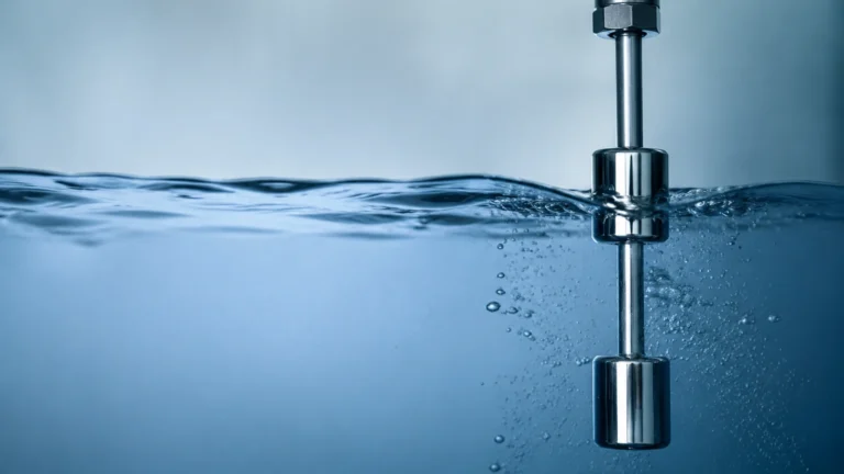
Unlike continuous transmitters, point level switches only detect the presence or absence of liquid at a specific height. Tuning fork switches vibrate at a specific frequency; when submerged, the frequency shifts, triggering an alarm.
* Application in Cat 3: Highly reliable as secondary "High-High" sensors in an AOPS because they provide a simple, robust binary signal.
Practical Selection Table for Category 3 Level Sensors
When designing a system for API 2350 5th edition sensor independence category 3 tanks, the following table helps compare common technologies used for TGS and AOPS roles.
| Technology | Role (TGS/AOPS) | Accuracy | Maintenance | Suitability for Cat 3 |
| :— | :— | :— | :— | :— |
| Non-Contact Radar | Primary TGS | Excellent | Low | High (Best for primary measurement) |
| Guided Wave Radar | TGS or AOPS | High | Low | High (Excellent for independent AOPS) |
| Tuning Fork Switch | AOPS Only | N/A (Point) | Low | High (Redundant safety layer) |
| Hydrostatic Press. | TGS | Moderate | Medium | Medium (Density dependent) |
| Ultrasonic | TGS | Moderate | Low | Low (Vapor sensitive) |
| Magnetic Gauge | Visual/AOPS | Moderate | Medium | Medium (Mechanical parts) |
Implementation Requirements for Category 3 Compliance
Transitioning a tank to Category 3 status involves more than just installing two sensors. The API 2350 5th edition emphasizes the "Safety Life Cycle," which includes:
1. Risk Assessment: Conduct a formal study to determine the required Safety Integrity Level (SIL). Most AOPS in Category 3 applications are designed to meet SIL 1 or SIL 2 standards.
2. Response Time Calculation: The system must be able to detect a high-high level and completely close the inlet valves before the tank reaches its critical high level (the point of structural failure or overflow). This calculation must account for maximum flow rates.
3. Proof Testing: API 2350 requires regular proof testing of the AOPS. This involves verifying that the sensor, logic solver, and final control element (valve) all function correctly. Modern instruments with remote proof-testing capabilities are preferred to reduce the need for climbing tanks.
4. Redundancy vs. Independence: While redundancy (using two of the same sensors) increases reliability, API 2350 5th edition prioritizes independence. Using diverse technologies (e.g., a Radar for TGS and a Tuning Fork for AOPS) is a best practice to avoid common-mode failures.
Installation and Maintenance Considerations
Proper installation is critical to maintaining the integrity of an independent sensor system. Consider the following engineering guidelines:
* Nozzle Location: Ensure that the AOPS sensor is not located directly under a fill pipe, where turbulent product or splashing could cause a false high-high trigger.
* Stilling Wells: For tanks with internal agitators or high turbulence, installing sensors within stilling wells or bypass chambers can provide a more stable surface for measurement.
* Environmental Protection: Level transmitters should be equipped with sunshades in extreme climates to prevent electronic overheating and signal drift.
* Calibration: While radar and ultrasonic sensors are factory-calibrated, they must be field-verified during commissioning to ensure the "zero" and "span" points align with the tank's physical geometry.
Frequently Asked Questions (FAQs)
Q: Can I use a single multi-variable sensor for both TGS and AOPS in a Category 3 tank?
A: Generally, no. API 2350 5th edition emphasizes sensor independence. Using a single device, even if it has dual outputs, introduces a single point of failure. If the sensor head fails, both systems fail.
Q: Is SIL certification mandatory for Category 3 tanks?
A: While API 2350 does not strictly mandate SIL certification for all tanks, it strongly recommends following functional safety standards (like IEC 61511). Most modern AOPS installations for Category 3 are designed to SIL 2 standards to ensure maximum risk reduction.
Q: How often should I proof-test my independent overfill sensors?
A: The frequency is determined by the risk assessment and the manufacturer's recommendations, but typically it ranges from once every six months to once a year. The 5th edition places a heavy emphasis on documenting these tests.
Q: Does API 2350 apply to underground tanks?
A: No, API 2350 specifically applies to above-ground, atmospheric storage tanks at petroleum facilities. Underground tanks are usually covered by different regional environmental regulations.
Conclusion
Achieving compliance with API 2350 5th edition sensor independence category 3 tanks requires a disciplined approach to instrumentation selection and system design. By ensuring that the Automated Overfill Prevention System is physically and functionally independent of the Tank Gauging System, facilities can prevent catastrophic spills and protect both personnel and the environment. When selecting hardware, engineers should prioritize technologies like radar and robust point-level switches that offer high reliability and minimal maintenance requirements. For further technical specifications on industrial level measurement solutions, visit the Main Page to explore professional instrumentation options.
Download API 2350 5th Edition Sensor Independence Category 3 Tanks as a PDF