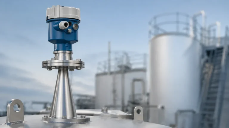
Intrinsically Safe Ultrasonic Level Sensor
Intrinsically Safe Ultrasonic Level Sensor
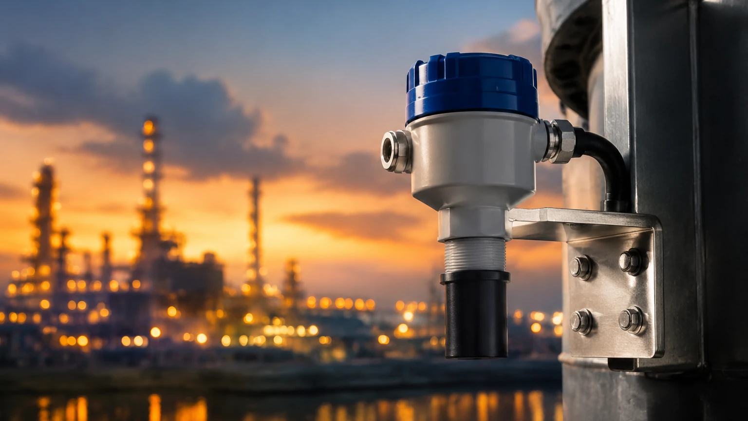
In industrial environments where flammable gases, vapors, or combustible dusts are present, the selection of instrumentation is governed by strict safety standards. The intrinsically safe ultrasonic level sensor represents a critical solution for these hazardous areas, combining the advantages of non-contact measurement with electronic designs that prevent ignition. This guide provides a technical overview of the measurement principles, safety certifications, selection criteria, and installation best practices for these instruments.
Measurement Principle of Ultrasonic Sensors
Ultrasonic level measurement is based on the "Time of Flight" (ToF) principle. The sensor, typically mounted at the top of a tank or vessel, contains a piezoelectric transducer that converts electrical energy into mechanical vibrations. These vibrations create high-frequency sound pulses—usually in the range of 20 kHz to 70 kHz—which are emitted toward the material surface.
The Calculation Process
Once the sound pulse is transmitted, it travels through the air (or gas) in the tank, reflects off the surface of the liquid or solid, and returns to the transducer. The sensor acts as both a transmitter and a receiver. The internal electronics measure the time interval between the emission of the pulse and the reception of the echo.
The distance from the sensor to the material surface is calculated using the formula:
Distance = (Speed of Sound × Time) / 2
Since the speed of sound in air is approximately 343 meters per second (at 20°C), the sensor can determine the distance with high precision. By knowing the total height of the vessel (the "Empty" calibration point), the transmitter subtracts the measured distance from the vessel height to provide the actual level or volume of the contents.
Signal Processing and Echo Filtering
Modern sensors utilize advanced digital signal processing (DSP) to distinguish the true level echo from false reflections caused by internal tank obstructions such as agitators, ladders, or pipes. This process, often referred to as "echo mapping" or "false echo suppression," allows the sensor to ignore static obstacles and focus only on the moving surface of the medium.
Understanding Intrinsic Safety (IS)
Intrinsic safety is a protection technique for the safe operation of electronic equipment in hazardous areas by limiting the energy, both electrical and thermal, available for ignition. Unlike explosion-proof enclosures, which are designed to contain an internal explosion, an intrinsically safe ultrasonic level sensor is designed such that it cannot produce a spark or heat sufficient to ignite an explosive atmosphere, even under fault conditions.
Safety Ratings and Zones
Hazardous areas are classified into zones based on the frequency and duration of the occurrence of an explosive atmosphere:
* Zone 0: An area in which an explosive atmosphere is present continuously or for long periods.
* Zone 1: An area in which an explosive atmosphere is likely to occur in normal operation.
* Zone 2: An area in which an explosive atmosphere is not likely to occur in normal operation but, if it does, will persist for a short period only.
An intrinsically safe ultrasonic level sensor rated as "Ex ia" is suitable for Zone 0, 1, and 2, while an "Ex ib" rating is typically limited to Zone 1 and 2. These certifications (such as ATEX in Europe or IECEx internationally) ensure that the device has been tested to meet rigorous safety standards.
The Role of Associated Apparatus
To maintain the integrity of an intrinsically safe circuit, the sensor must be connected to an associated apparatus located in a safe area. This is usually a Zener barrier or a galvanic isolator. These devices limit the voltage and current sent to the sensor in the hazardous area, ensuring that even if a cable is cut or a short circuit occurs, the energy remains below the ignition threshold.
Key Features and Evaluation Criteria
When evaluating an intrinsically safe ultrasonic level sensor for a specific application, several technical specifications must be prioritized to ensure both accuracy and safety.
1. Measurement Range: Sensors are typically available for ranges from 0.25 meters up to 15 or 20 meters. It is essential to select a sensor where the expected level fluctuations fall within the optimal sensitivity range of the transducer.
2. Chemical Compatibility: The transducer face (the wetted part) must be resistant to the vapors in the tank. Common materials include Polypropylene (PP), Polyvinylidene Fluoride (PVDF), and Synthetic Rubber. PVDF is often preferred for aggressive chemical environments.
3. Beam Angle: The beam angle defines the spread of the ultrasonic pulse. A narrower beam angle (e.g., 5° to 10°) is better for tall, narrow tanks or vessels with internal obstructions, as it minimizes the risk of hitting the tank walls.
4. Temperature Compensation: The speed of sound varies with air temperature (changing by approximately 0.17% per degree Celsius). High-quality sensors include an integrated temperature sensor to automatically compensate for these changes, maintaining accuracy across varying process conditions.
5. Output Options: Most industrial sensors provide a 4-20mA analog signal, often with HART (Highway Addressable Remote Transducer) protocol for digital communication, allowing for remote configuration and diagnostics.
Practical Selection Table
The following table provides a general comparison of common configurations for intrinsically safe ultrasonic sensors in industrial applications.
| Feature | Standard Water/Wastewater | Chemical Storage (Corrosive) | Fuel/Oil Storage |
| :— | :— | :— | :— |
| Typical Range | 0.5m – 10m | 0.25m – 6m | 0.3m – 12m |
| Wetted Material | Polypropylene (PP) | PVDF | PVDF or Stainless Steel |
| Safety Rating | ATEX Zone 1 (Ex ib) | ATEX Zone 0 (Ex ia) | ATEX Zone 0 (Ex ia) |
| Accuracy | ±0.25% of Range | ±0.2% of Range | ±0.25% of Range |
| Operating Temp | -20°C to +60°C | -40°C to +80°C | -40°C to +70°C |
| Pressure Limit | Atmospheric | Up to 2 Bar (29 PSI) | Up to 3 Bar (43 PSI) |
Installation and Engineering Considerations
Correct installation is paramount for the reliable performance of an ultrasonic sensor. Engineers should adhere to the following guidelines:
The Blocking Distance (Dead Zone)
Every ultrasonic sensor has a "blocking distance" or "dead zone" immediately in front of the transducer face. In this zone (typically 0.2m to 0.5m depending on the frequency), the sensor cannot accurately process the returning echo because the transducer is still vibrating from the transmission pulse. The sensor must be mounted high enough so that the maximum liquid level never enters this dead zone.
Mounting Position and Orientation
* Perpendicularity: The sensor must be mounted perpendicular to the liquid surface. Even a small tilt can cause the sound pulse to reflect away from the transducer, resulting in signal loss.
* Wall Distance: To avoid interference from wall reflections, the sensor should be placed at a distance from the tank wall at least 1/6th of the tank height.
* Inflow Avoidance: Never mount the sensor directly above the tank's filling inlet. The turbulence and falling liquid will disrupt the ultrasonic signal and cause erratic readings.
Hazardous Area Wiring
When installing an intrinsically safe ultrasonic level sensor, use shielded, twisted-pair cabling. The shield should be grounded only at the safe-area end (at the barrier or isolator) to prevent ground loops, which can introduce electrical noise into the sensitive measurement circuit.
Limitations and Environmental Factors
While ultrasonic technology is versatile, it is not suitable for every application. Understanding its limitations prevents costly engineering errors.
* Vacuum Applications: Sound waves require a medium (gas) to travel. Therefore, ultrasonic sensors cannot function in a vacuum.
* Heavy Foam: Thick, dense foam on the surface of a liquid can absorb the ultrasonic pulse rather than reflecting it. In such cases, the sensor may report a "Loss of Echo" (LOE) or provide inaccurate readings. If foam is a persistent issue, a radar level meter or a contact-based technology may be more appropriate.
* High Dust or Vapor: While light dust is manageable, extremely dense dust or heavy steam can attenuate the signal. High-frequency sensors (shorter range) are generally more susceptible to this than low-frequency sensors (longer range).
* Pressure Extremes: Standard ultrasonic sensors are designed for atmospheric or near-atmospheric pressure. High pressure changes the density of the gas, which significantly alters the speed of sound and can exceed the mechanical limits of the transducer housing.
Frequently Asked Questions (FAQs)
Q: Can I use an intrinsically safe sensor without a Zener barrier?
A: No. The "intrinsically safe" certification of the sensor is only valid when it is part of a certified IS system, which includes the sensor, the cable, and the safety barrier or isolator. Using the sensor without these components voids the safety rating and creates a significant explosion risk.
Q: How does wind or air movement affect the measurement?
A: In outdoor applications or tanks with heavy ventilation, strong air currents can "blow" the ultrasonic pulse away, leading to signal instability. Using a stilling well can help mitigate this effect by providing a protected column of air for the measurement.
Q: What is the difference between a 2-wire and 4-wire sensor?
A: A 2-wire sensor is loop-powered, meaning the same two wires carry both the power supply and the 4-20mA output signal. This is the most common configuration for intrinsically safe applications because it simplifies wiring and reduces the energy footprint. 4-wire sensors have separate pairs for power and signal, which is usually reserved for high-power devices that are not intrinsically safe.
Q: Does the color of the liquid affect the sensor?
A: No. Since the sensor uses sound waves rather than light, the color, transparency, or opacity of the liquid has no impact on the measurement accuracy.
Conclusion
The intrinsically safe ultrasonic level sensor is a cornerstone of modern industrial safety and process automation. By offering a non-contact, maintenance-free method of monitoring levels in volatile environments, it protects both personnel and assets. When selecting a device, engineers must carefully consider the hazardous zone classification, the chemical nature of the process media, and the physical geometry of the vessel. For a comprehensive range of level measurement technologies and technical support, professionals are encouraged to Review product options and application support at the Welk Main Page.
Download Intrinsically Safe Ultrasonic Level Sensor as a PDF