Contacting Conductivity Sensor
Contacting Conductivity Sensor
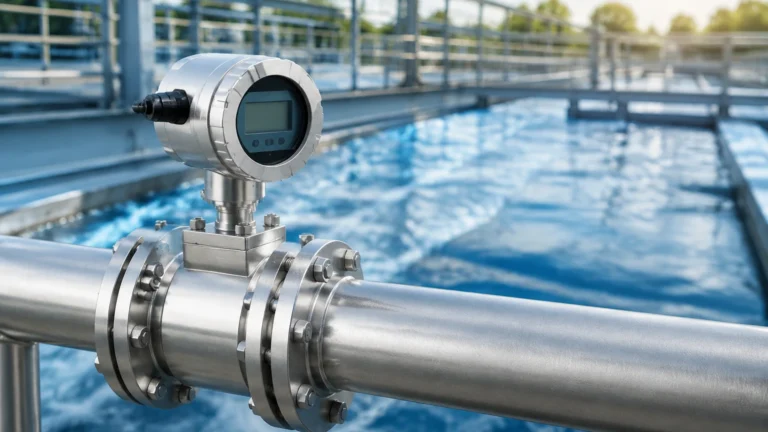
In industrial liquid analysis, the contacting conductivity sensor remains a cornerstone technology for monitoring water quality, chemical concentration, and process purity. Unlike inductive (toroidal) methods that use magnetic fields, a contacting conductivity sensor relies on direct physical contact between its electrodes and the process medium. This direct interaction allows for extreme sensitivity, particularly in low-conductivity applications such as deionized water or boiler condensate return.
For engineers and plant operators, selecting the right sensor involves understanding the relationship between electrode geometry, material science, and the specific electrical properties of the fluid being measured. This guide provides a comprehensive technical overview of contacting conductivity technology, installation best practices, and selection criteria for industrial environments.
Fundamental Principles of Contacting Conductivity Measurement
Conductivity is the measure of a solution's ability to conduct an electrical current. In aqueous solutions, this current is carried by ions. A contacting conductivity sensor measures this ability by applying an alternating current (AC) voltage to two or more electrodes and measuring the resulting current.
Ohm’s Law and Conductance
The basic principle is derived from Ohm’s Law ($V = I \times R$). In liquid analysis, we focus on conductance ($G$), which is the reciprocal of resistance ($R$).
$$G = 1 / R = I / V$$
Where:
* G is conductance (measured in Siemens, S).
* I is current.
* V is voltage.
The Cell Constant (K)
Conductivity ($\\sigma$) is the conductance adjusted for the physical dimensions of the sensor. This physical geometry is defined as the "Cell Constant" ($K$). It is the ratio of the distance ($L$) between the electrodes to the cross-sectional area ($A$) of the electrodes.
$$K = L / A$$
The relationship between conductivity and conductance is expressed as:
$$\\sigma = G \times K$$
In practical applications, a sensor with a low cell constant (e.g., $K=0.01$ or $0.1$ cm⁻¹) has electrodes spaced closely together or with a large surface area, making it ideal for high-purity water. Conversely, a sensor with a high cell constant (e.g., $K=1.0$ or $10.0$ cm⁻¹) is designed for high-conductivity liquids like seawater or concentrated chemicals, as it prevents the electrical circuit from becoming saturated.
Types of Contacting Conductivity Sensors
Contacting sensors are generally categorized by the number of electrodes used in the measurement circuit. Each configuration has specific advantages depending on the conductivity range and the potential for electrode fouling.
Two-Electrode Sensors
This is the most common design for low-conductivity applications. It consists of two electrodes (often concentric or parallel) with a known cell constant.
* Advantages: Simple design, high accuracy in low-range measurements (up to 20 mS/cm), and relatively low cost.
* Limitations: Susceptible to "polarization error" at high conductivity levels and sensitive to electrode fouling or coating.
Four-Electrode Sensors
To overcome the limitations of the two-electrode design in higher conductivity ranges, the four-electrode (or four-pole) sensor was developed. It utilizes two drive electrodes that pass current through the liquid and two sensing electrodes that measure the voltage drop.
* Advantages: Virtually eliminates polarization errors and is much more resistant to the effects of electrode fouling. It can cover a much wider range of conductivity with a single sensor.
* Limitations: More complex electronics required and typically more expensive than two-electrode versions.
Material Selection and Chemical Compatibility
The durability of a contacting conductivity sensor depends heavily on the materials used for the electrodes and the insulating body. Because the electrodes are in direct contact with the process fluid, they must withstand chemical corrosion and physical abrasion.
1. 316L Stainless Steel: The standard for most water treatment and general industrial applications. It offers good corrosion resistance and mechanical strength.
2. Titanium: Preferred for highly corrosive environments or where stainless steel might leach metal ions into the process (e.g., in semiconductor manufacturing).
3. Graphite: Often used in high-conductivity or wastewater applications. Graphite electrodes are resistant to many chemicals but are more brittle than metal.
4. Insulator Materials: The body of the sensor is typically made from PEEK (Polyether ether ketone), PTFE (Teflon), or CPVC. PEEK is favored for high-temperature and high-pressure applications due to its exceptional thermal stability.
Engineering Selection Criteria
When specifying a contacting conductivity sensor for a project, engineers must evaluate the following parameters to ensure long-term reliability and accuracy.
Measurement Range
The expected conductivity range is the primary factor in determining the required cell constant.
| Conductivity Range | Recommended Cell Constant (K) | Typical Application |
| :— | :— | :— |
| 0.055 µS/cm to 20 µS/cm | 0.01 cm⁻¹ | Ultrapure Water (UPW), DI Water |
| 1 µS/cm to 200 µS/cm | 0.1 cm⁻¹ | Condensate, RO Water, Distilled Water |
| 10 µS/cm to 2,000 µS/cm | 1.0 cm⁻¹ | Potable Water, Cooling Tower Water |
| 100 µS/cm to 20,000 µS/cm | 10.0 cm⁻¹ | Brackish Water, Chemical Dilution |
Temperature Compensation
Conductivity is highly temperature-dependent; for most aqueous solutions, conductivity increases by approximately 2% per degree Celsius. Therefore, an integrated temperature element (such as a Pt100 or Pt1000 RTD) is essential. The transmitter uses this data to calculate the "Temperature Compensated Conductivity," usually referenced to 25°C (77°F).
Pressure and Temperature Ratings
Industrial processes often operate at elevated pressures. Ensure the sensor is rated for the maximum process pressure (e.g., 10 bar / 145 psi) and temperature (e.g., 120°C / 248°F). High-pressure steam applications may require specialized boiler-grade sensors.
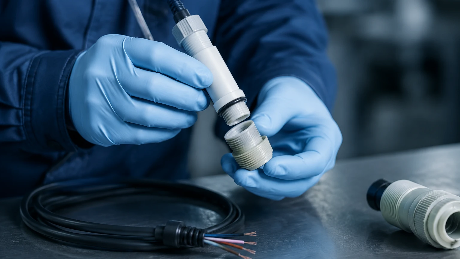
Installation Best Practices and Considerations
Proper installation is critical to obtaining accurate readings. A contacting conductivity sensor that is incorrectly positioned may suffer from air entrapment or inadequate flow, leading to erratic data.
1. Full Submersion: The sensor electrodes must be completely submerged in the liquid at all times. In partially filled pipes, install the sensor at the bottom or in a "U-trap" to ensure it remains wet.
2. Avoid Air Bubbles: Air is a perfect insulator. If bubbles collect on the electrode surface, the measured conductivity will drop significantly. Install sensors in vertical pipe runs with upward flow to allow bubbles to escape.
3. Flow Direction: For flow-through installations, the liquid should enter the sensor's measurement cell and exit freely. Ensure there are no "dead zones" where stagnant liquid can accumulate.
4. Orientation: Sensors should ideally be installed at a 90-degree angle to the flow or at a slight upward angle to prevent sediment from settling inside the electrode chamber.
5. Cable Runs: Conductivity signals (especially at low ranges) are high-impedance and sensitive to electromagnetic interference (EMI). Use shielded cables and avoid routing them near high-voltage power lines or variable frequency drives (VFDs).
Limitations and Maintenance
While highly accurate, contacting conductivity sensors have inherent limitations compared to non-contacting methods.
* Fouling and Coating: Since the electrodes touch the fluid, any oil, biological growth, or scale that coats the electrodes will act as an insulator, resulting in a lower-than-actual conductivity reading. Regular cleaning with a mild detergent or dilute acid is often necessary.
* Polarization: At high conductivities, a layer of ions can build up at the electrode surface (the "double layer"), creating an additional resistance that skews the measurement. This is why contacting sensors are generally limited to conductivities below 20-50 mS/cm unless a four-electrode design is used.
* Mechanical Wear: In abrasive slurries, the electrodes can be physically worn down, which changes the cell constant over time and necessitates recalibration or replacement.
For comprehensive process control, conductivity data is often paired with level measurement. In tanks and vessels where chemical concentration is monitored via conductivity, accurate level data is required to manage volumes and prevent dry-run conditions for the sensors. You can Review product options and application support to see how various level measurement technologies, such as radar or ultrasonic sensors, integrate into these industrial monitoring systems.
Frequently Asked Questions (FAQs)
Q: How often should I calibrate my contacting conductivity sensor?
A: Calibration frequency depends on the process environment. In clean water applications, semi-annual or annual calibration may suffice. In processes prone to fouling, monthly checks against a known standard solution are recommended.
Q: Can I use a contacting sensor for concentrated sulfuric acid?
A: Generally, no. Concentrated acids have very high conductivity and are often corrosive to standard electrodes. An inductive (toroidal) conductivity sensor is typically the better choice for high-concentration chemicals and acids.
Q: What is the difference between "Conductivity" and "TDS"?
A: Conductivity measures the ability to pass current, while TDS (Total Dissolved Solids) is the mass of dissolved minerals in a given volume. Many transmitters can convert conductivity to TDS using a linear multiplier (typically 0.5 to 0.7), but this is an estimate based on the expected ion types.
Q: Why is my reading drifting over time?
A: Drift is most commonly caused by electrode coating or a failing temperature compensator. If cleaning the sensor does not resolve the drift, check the integrity of the cable connections and the transmitter's temperature input.
Conclusion
The contacting conductivity sensor is an indispensable tool for high-precision liquid analysis in the B2B industrial sector. By understanding the nuances of cell constants, material compatibility, and the physical requirements of the installation, engineering teams can ensure accurate process control and protect critical equipment from the effects of poor water quality or incorrect chemical concentrations. When combined with reliable level measurement solutions, these sensors provide the data necessary for efficient and safe industrial automation.