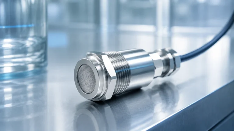
Turbidity Measurement Device
Turbidity Measurement Device
In industrial process control and environmental monitoring, a turbidity measurement device is an essential instrument used to quantify the clarity of a liquid. Turbidity is not a direct measure of the concentration of suspended particles but rather an optical characteristic that indicates how much light is scattered or absorbed by materials in the water or solution. These materials can include clay, silt, finely divided inorganic and organic matter, soluble colored organic compounds, and plankton and other microscopic organisms.
For engineers and plant managers operating in water treatment, chemical processing, and food and beverage production, selecting the correct turbidity measurement device is critical for ensuring product quality and regulatory compliance. This guide explores the technical principles, selection criteria, and practical installation strategies for these instruments.
Understanding Turbidity Measurement Principles
Before selecting a turbidity measurement device, it is vital to understand the optical physics involved. The measurement is typically performed by passing a light beam through a sample and measuring the light intensity at a specific angle relative to the incident beam.
Nephelometry (90-degree Scattering)
This is the most common method for measuring low to medium turbidity. According to the ISO 7027 and EPA 180.1 standards, a light source (either an Infrared LED or a Tungsten lamp) sends a beam into the fluid. A detector is placed at a 90-degree angle to the light source. As particles encounter the light, they scatter it in all directions; the detector measures the intensity of the light scattered at that specific 90-degree angle. The unit of measure is typically the Nephelometric Turbidity Unit (NTU) or Formazin Nephelometric Unit (FNU).
Attenuation (Transmission Method)
For highly turbid liquids where the particle concentration is so high that light cannot penetrate deeply, the attenuation method is used. In this setup, the detector is placed directly opposite the light source (180 degrees). The device measures the amount of light that passes through the sample without being scattered or absorbed. This is often used in wastewater sludge applications or high-concentration chemical slurries.
Backscatter Method
In extremely dense fluids, some sensors measure light scattered back at an angle greater than 90 degrees (often 135 degrees). This is particularly useful in industrial processes where the liquid is nearly opaque, and the goal is to monitor high-solids concentrations.
Key Evaluation Criteria for a Turbidity Measurement Device
When evaluating a turbidity measurement device for industrial use, several technical factors must be prioritized to ensure long-term accuracy and minimal maintenance.
1. Measurement Range: Devices are often optimized for either low-range (0–10 NTU) for drinking water or high-range (up to 4,000+ NTU) for industrial discharge. Ensure the sensor's linear range matches your process requirements.
2. Light Source Selection:
* Infrared (IR) LED (860 nm): Preferred under ISO 7027 standards. It minimizes the interference caused by the color of the liquid, making it ideal for colored wastewater.
* White Light (Tungsten): Preferred under US EPA 180.1. It is more sensitive to small particles but can be affected by the color of the sample.
3. Sensor Housing and Materials: For chemical applications, the wetted parts must be resistant to corrosion. Common materials include PVC, 316L Stainless Steel, or Titanium. The optical window is typically made of sapphire or specialized glass to resist scratching during cleaning.
4. Automatic Cleaning Systems: In many B2B applications, fouling of the optical window is the primary cause of measurement drift. Integrated wipers or ultrasonic cleaning modules are essential for reducing manual maintenance cycles.
Selection Guide: Matching Technology to Application
The following table provides a general framework for selecting a turbidity measurement device based on the specific industrial environment.
| Application | Typical Range | Recommended Principle | Key Feature Needed |
| :— | :— | :— | :— |
| Drinking Water Treatment | 0–5 NTU | Nephelometric (90°) | High resolution, low stray light |
| Cooling Water Monitoring | 0–50 NTU | Nephelometric (90°) | Corrosion-resistant housing |
| Wastewater Effluent | 10–500 NTU | Nephelometric or Dual Beam | Automatic wiper/cleaning |
| Sludge Concentration | 1,000+ NTU | Attenuation or Backscatter | High solids tolerance |
| Food & Beverage (CIP) | 0–1,000 NTU | 90° / 180° Hybrid | Hygienic (Tri-clamp) fittings |
For organizations looking to integrate these sensors into a broader automation framework, reviewing modern instrumentation options is recommended. You can find comprehensive details on compatible industrial sensors on the Welk Main Page.
Installation Best Practices for Reliable Monitoring
A turbidity measurement device is highly sensitive to the environment in which it is installed. Improper placement can lead to false readings and frequent alarms.
Bubble Management
Air bubbles are the "enemy" of turbidity measurement. Because bubbles scatter light just like solid particles, they will cause a positive bias (falsely high readings). To mitigate this:
* Install the sensor in a pressurized line if possible, which keeps air in solution.
* Use a de-bubbler or a flow cell with a baffle system if measuring at atmospheric pressure.
* Avoid installing sensors at the highest point of a pipe loop where air tends to collect.
Flow Rate and Orientation
The flow rate should be high enough to prevent particles from settling on the sensor face but not so high that it creates cavitation or turbulence that generates bubbles. In a pipe installation, the sensor should ideally be placed on the side (3 o'clock or 9 o'clock position) rather than the bottom, where sediment collects, or the top, where air pockets reside.
Ambient Light Interference
While most modern turbidity measurement devices use modulated light to filter out ambient noise, extreme sunlight or bright overhead industrial lighting can still interfere with the detector. Ensure the sensor is shielded or installed in an opaque flow cell.

Limitations and Risk Mitigation in Process Environments
Despite their accuracy, turbidity measurement devices have inherent limitations that must be managed through engineering controls.
* Particle Size Sensitivity: Nephelometric devices are more sensitive to smaller particles, while attenuation devices are more sensitive to larger particles. If the particle size distribution in your process changes significantly, the NTU reading may change even if the total suspended solids (TSS) concentration remains constant.
* Color Interference: If using a white light source, a "tea-colored" liquid will absorb some of the light, leading to a falsely low turbidity reading. Switching to an Infrared (IR) source is the standard mitigation for this risk.
* Fouling (Bio-growth and Scaling): In wastewater or untreated surface water, biofilms can grow on the optical lens within days. Regular calibration checks and the use of automated wipers are the only effective ways to maintain data integrity.
Frequently Asked Questions (FAQs)
Q: How often should a turbidity measurement device be calibrated?
A: In stable drinking water applications, quarterly calibration is often sufficient. However, in high-fouling industrial processes, a monthly check or even weekly verification with a secondary standard (like Formazin or stabilized Formazin) is recommended.
Q: What is the difference between NTU and FNU?
A: While they are often used interchangeably, NTU (Nephelometric Turbidity Units) usually refers to measurements taken with a white light source (EPA 180.1), whereas FNU (Formazin Nephelometric Units) refers to measurements taken with an Infrared light source (ISO 7027).
Q: Can turbidity be used to measure Total Suspended Solids (TSS)?
A: Yes, but only through correlation. You must take laboratory TSS samples and compare them to the turbidity readings to create a site-specific conversion curve. This curve is only valid as long as the particle type and size remain consistent.
Q: Does pipe material affect the measurement?
A: If the sensor is an immersion type placed directly in a pipe, the internal reflection from the pipe walls can cause "stray light" errors. Using a matte-black lined flow cell or a large diameter pipe (at least 100 mm or 4 inches) helps minimize this effect.
Conclusion
Selecting and maintaining a turbidity measurement device requires a balance between understanding the optical physics of the fluid and the mechanical realities of the installation site. By choosing the correct light source, ensuring proper bubble management, and implementing a robust cleaning regimen, industrial operators can achieve precise and reliable data for process optimization. For further technical specifications on industrial level and analytical measurement solutions, professionals are encouraged to review the product options and application support available on the manufacturer's Main Page.