Instrument Calibration
Instrument Calibration
In the landscape of industrial automation and process control, the accuracy of level measurement is a cornerstone of operational safety, efficiency, and regulatory compliance. Instrument calibration is the documented process of comparing a measurement device—the instrument under test—against a traceable reference standard of known accuracy. For level measurement instruments, this ensures that the signal transmitted to a control system accurately reflects the physical volume or height of the material within a vessel.
Whether managing volatile chemicals, wastewater, or high-pressure steam, the reliability of a level sensor depends not just on its internal technology, but on how precisely it is calibrated to the specific environment of the application. This guide examines the principles of level measurement, the methodologies of instrument calibration, and practical considerations for maintaining peak performance in industrial settings.
Understanding Level Measurement Principles
Before addressing the specifics of instrument calibration, it is essential to understand the underlying physics of the instruments being calibrated. Different technologies interact with the process media in unique ways, necessitating different calibration approaches.
Radar Level Measurement
Radar level meters operate on the Time-of-Flight (ToF) principle. They emit electromagnetic pulses (either via Pulse Radar or Frequency Modulated Continuous Wave – FMCW) that travel at the speed of light. These pulses reflect off the surface of the medium and return to the sensor. The distance is calculated based on the time interval between transmission and reception.
In radar systems, calibration focuses on defining the "Zero" point (usually the tank bottom or the end of a probe) and the "Full" or "Span" point (the maximum desired level). Because electromagnetic waves are largely unaffected by air temperature or pressure, radar is often considered one of the most stable technologies, though the dielectric constant of the material can influence signal strength.
Ultrasonic Level Measurement
Similar to radar, ultrasonic sensors use ToF but employ sound waves instead of electromagnetic waves. A transducer emits an ultrasonic pulse that reflects off the liquid surface. However, the speed of sound is highly dependent on the temperature and density of the air through which it travels. Calibration for ultrasonic devices must include temperature compensation factors to ensure that fluctuations in the headspace do not result in false level readings.
Hydrostatic Level Measurement
Hydrostatic transmitters measure the pressure exerted by a liquid column. The principle is based on the formula: $P = \rho \cdot g \cdot h$, where $P$ is pressure, $\rho$ is the fluid density, $g$ is gravity, and $h$ is the height of the liquid. Calibration for these instruments is essentially a pressure-to-level conversion. If the density of the fluid changes due to temperature or concentration shifts, the instrument will require recalibration to maintain accuracy.
Magnetic Level Gauges
Magnetic level gauges utilize a float containing an internal magnet assembly that moves with the liquid level. This float interacts with an external indicator or a transmitter. Calibration here is often mechanical, ensuring the float's buoyancy matches the specific gravity of the fluid, and electronic, ensuring the transmitter's reed switches or magnetostrictive sensors align with the physical 0% and 100% marks.
The Fundamentals of Instrument Calibration
Instrument calibration in a B2B industrial context typically involves establishing a relationship between the measured physical quantity and the output signal, which is most commonly a 4-20 mA analog loop or a digital protocol like HART, Profibus, or Foundation Fieldbus.
Zero and Span Calibration
The most common form of calibration is the "two-point" adjustment:
1. Zero Calibration (4 mA): This represents the empty state of the vessel. For a hydrostatic sensor, this is atmospheric pressure. For a radar sensor, this is the distance from the flange to the bottom of the tank.
2. Span Calibration (20 mA): This represents the full state of the vessel. It is critical to define this point below the "dead zone" or "blocking distance" of the sensor to avoid signal loss.
Dry vs. Wet Calibration
* Dry Calibration: This is performed without filling the tank. It involves inputting theoretical values into the instrument’s microprocessor using a handheld communicator or laptop. For example, telling a radar meter that the tank is 10 meters deep.
* Wet Calibration: This is the most accurate method, involving the actual filling and emptying of the vessel to specific levels. The instrument's output is compared against physical measurements (such as a dip tape or sight glass) at multiple points (e.g., 0%, 25%, 50%, 75%, and 100%).
Calibration Procedures for Different Technologies
Each instrument type requires a specific set of steps to ensure the calibration is valid and traceable.
Radar and Ultrasonic (Non-Contact)
For non-contact sensors, the calibration must account for the "Reference Point," which is usually the lower edge of the flange or the sensor face.
* Step 1: Establish the "Basic Adjustment" by entering the tank height (E) and the calibration distance (F).
* Step 2: Map the "False Echo Storage." This is a critical calibration step where the sensor identifies static internal structures (like ladders or agitators) and ignores their reflections.
* Step 3: Verify the reading against a manual tape measure at the 50% mark.
Hydrostatic Transmitters
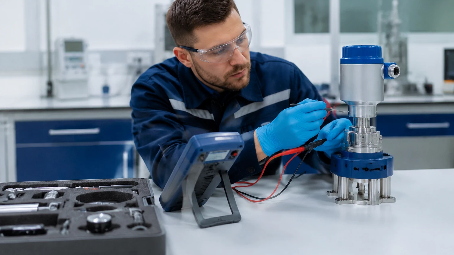
Calibration for hydrostatic sensors often occurs in a laboratory or on-site using a deadweight tester or a calibrated pressure pump.
* Step 1: Apply zero pressure and trim the output to 4.000 mA.
* Step 2: Apply the maximum calculated pressure (based on the height and density of the fluid) and trim the output to 20.000 mA.
* Step 3: Perform a linearity check by applying 25%, 50%, and 75% of the pressure range.
Selection Criteria and Comparison Table
When selecting a level instrument, the ease and frequency of instrument calibration should be a primary factor in the decision-making process. Some technologies are "set and forget," while others require periodic verification due to drift.
| Technology | Calibration Method | Difficulty | Frequency | Primary Calibration Variable |
| :— | :— | :— | :— | :— |
| Guided Wave Radar | Digital (HART/Laptop) | Low | Low | Distance/Dielectric |
| Non-Contact Radar | Digital/Echo Mapping | Medium | Low | Distance/Obstructions |
| Ultrasonic | Digital/Keypad | Low | Medium | Speed of Sound/Temp |
| Hydrostatic | Pressure Source | High | Medium | Fluid Density/Pressure |
| Magnetic Gauge | Mechanical/Visual | Low | Low | Specific Gravity |
| Level Switches | Sensitivity Potentiometer| Low | Annual | Interface/Sensitivity |
For engineers looking to optimize their process, it is helpful to Review product options and application support to determine which technology offers the best balance of accuracy and maintenance requirements for their specific site conditions.
Installation Considerations Impacting Calibration
Even a perfectly calibrated instrument will fail if the installation is flawed. Calibration and installation are inextricably linked in industrial level measurement.
1. Nozzle Dimensions: For radar and ultrasonic sensors, the height and diameter of the mounting nozzle can create parasitic reflections. Calibration must "tune out" these reflections.
2. Stilling Wells: If a tank has heavy foam or turbulence, a stilling well (a vertical pipe) is used. The calibration must then be adjusted to account for the restricted signal path and potential buildup on the pipe walls.
3. Atmospheric Venting: Hydrostatic sensors measuring open tanks must have their reference side vented to the atmosphere. If the vent is blocked, the zero-point calibration will drift as barometric pressure changes.
4. Specific Gravity Shifts: If a magnetic level gauge is calibrated for water ($
ho = 1000\text{ kg/m}^3$) but used for an oil with a density of $800\text{ kg/m}^3$, the float will sit lower in the liquid, causing a constant offset error. This must be corrected by recalibrating the transmitter scale or replacing the float.
Limitations and Common Challenges
Instrument calibration is not a panacea for all measurement issues. There are inherent limitations to what can be achieved through calibration alone.
* The "Dead Zone": Every ToF sensor has a minimum distance it can measure (often 0.1m to 0.5m). Calibration cannot overcome this physical limitation; it can only define how the instrument behaves when the level enters this zone.
* Hysteresis: In mechanical systems like level switches or magnetic gauges, the point at which a contact closes when the level is rising may differ from when it is falling. Calibration should find the mean point to minimize the impact of hysteresis.
* Environmental Drift: High-precision electronics are sensitive to extreme temperature swings. While modern instruments have internal compensation, annual instrument calibration is recommended for devices located in outdoor environments with significant seasonal variance.
* Build-up and Coating: If the process media coats the sensor (common in wastewater or slurry applications), the signal may be attenuated. Calibration can sometimes compensate for a thin film, but heavy build-up requires physical cleaning before a valid calibration can be performed.
Frequently Asked Questions (FAQs)
Q: How often should I perform instrument calibration on my level meters?
A: Most industrial standards (such as ISO 9001) suggest an annual calibration. However, for critical safety loops (SIL-rated systems), the interval may be shorter, while for non-critical monitoring, it may be extended to every two years based on historical drift data.
Q: Can I calibrate a radar level meter while the tank is in operation?
A: Yes, through "Dry Calibration" and software mapping. You can enter the known tank geometry and use echo-suppression features to ignore agitators or internal pipes without needing to empty the vessel. However, a manual check at a known level is always recommended for verification.
Q: Why does my hydrostatic level sensor show a negative reading when the tank is empty?
A: This is usually due to a zero-shift in the pressure cell or a change in atmospheric pressure if the vent tube is clogged. Re-zeroing the instrument (Zero Calibration) while the sensor is exposed to the atmosphere will typically resolve this.
Q: What is the difference between calibration and validation?
A: Calibration is the act of adjusting the instrument to match a standard. Validation (or verification) is the process of checking the instrument against a standard to see if it is still within its specified accuracy limits, without necessarily making adjustments.
Conclusion
Effective instrument calibration is a blend of scientific principle and practical engineering. By understanding the specific requirements of radar, ultrasonic, and hydrostatic technologies, maintenance teams can ensure that their level measurement systems provide the accurate data necessary for process optimization. Proper documentation of every calibration event is not only a requirement for quality audits but also a valuable tool for predictive maintenance, allowing engineers to identify declining sensor health before a failure occurs.
For detailed technical specifications and to explore a wide range of industrial level measurement solutions, visit the Main Page of our product catalog. Ensuring your instruments are correctly selected and calibrated is the first step toward a safer and more efficient industrial operation.