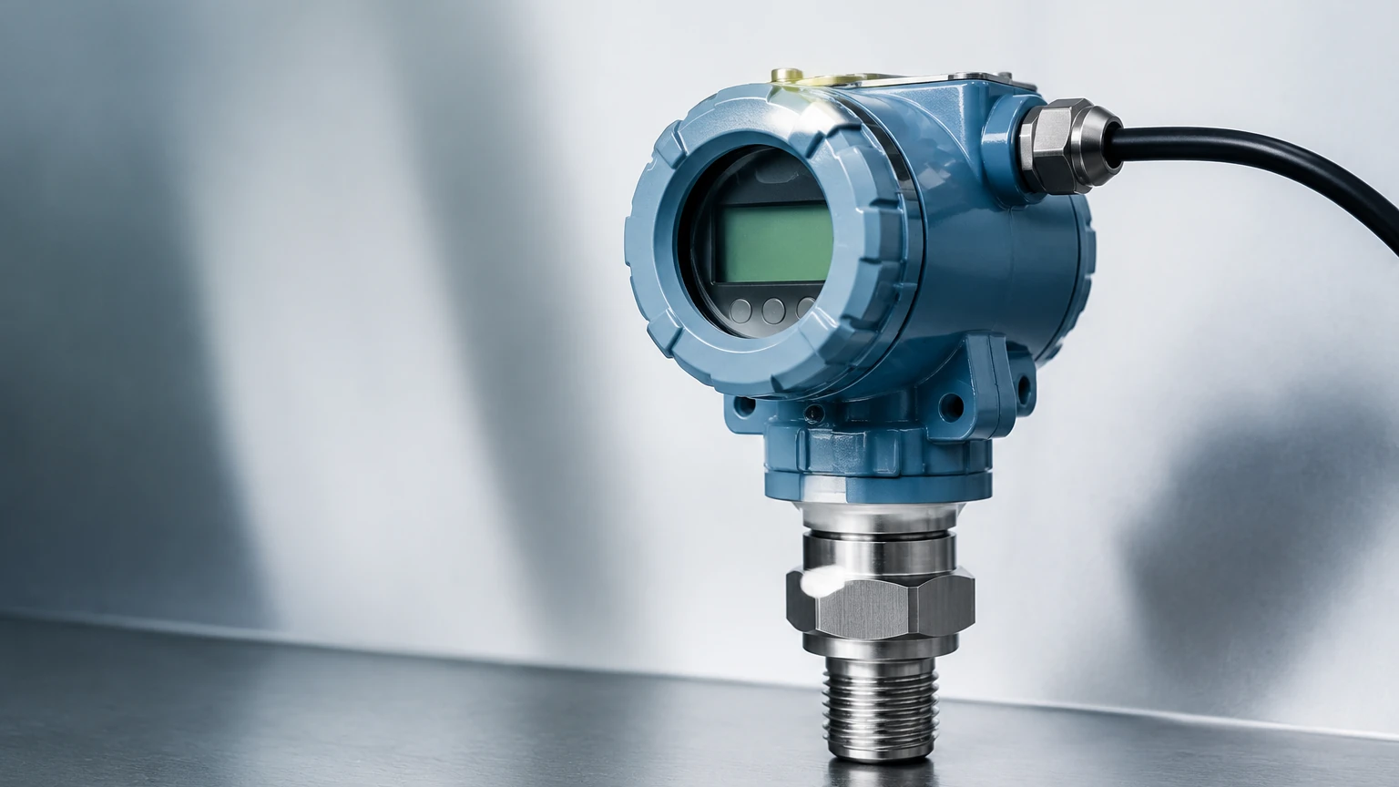
Pressure Transmitter with Indicator
Pressure Transmitter with Indicator
In industrial process control, the ability to monitor pressure and level accurately is fundamental to safety and efficiency. A pressure transmitter with indicator serves a dual purpose: it converts physical pressure into an electronic signal for remote monitoring while providing a real-time local display for field operators. This combination is essential in applications ranging from water treatment facilities to complex chemical processing plants where immediate visual verification is required at the point of measurement.
For engineers and project managers, selecting the right pressure transmitter with indicator involves understanding the underlying sensing technologies, the environmental demands of the installation site, and the integration requirements of the wider control system. As a professional manufacturer, Welk provides a range of these instruments designed to meet the rigorous standards of modern industrial automation.
Understanding the Pressure Transmitter with Indicator
A pressure transmitter is a transducer that measures the pressure of a fluid, gas, or vapor and converts it into an electrical signal, typically 4-20mA. When equipped with an indicator, the device includes a digital or analog display module integrated into the transmitter housing. This local display allows maintenance personnel to check process values without needing to access the central control room or use handheld communicators.
The indicator is often programmable, allowing users to view the pressure in various units such as bar, kPa, PSI, or even converted values like liquid level in meters or volume in liters. This versatility makes the pressure transmitter with indicator a cornerstone of hydrostatic level measurement and process pressure monitoring.
Measurement Principles and Signal Conversion
To select the appropriate instrument, it is vital to understand how pressure is sensed and processed. Most modern pressure transmitters utilize one of three primary sensing principles:
1. Piezoresistive Sensing
This is the most common technology for general-purpose industrial transmitters. It utilizes a silicon diaphragm with integrated resistors. When pressure is applied, the diaphragm deforms, changing the electrical resistance (the piezoresistive effect). This change is proportional to the pressure and is converted by the internal electronics into a standardized signal.
2. Capacitive Sensing
Capacitive pressure sensors use a sensing diaphragm and two capacitor plates. As pressure moves the diaphragm, the capacitance between the plates changes. This technology is highly sensitive and stable, making it ideal for low-pressure applications and vacuum measurement. It is also known for its robustness against overpressure events.
3. Hydrostatic Level Measurement
In many liquid storage applications, a pressure transmitter with indicator is used to determine the level of the liquid. The principle relies on the relationship between the height of the liquid column and the pressure at the bottom of the tank. The formula used is:
P = ρ × g × h
* P: Hydrostatic pressure (Pa)
* ρ: Density of the liquid (kg/m³)
* g: Acceleration due to gravity (approx. 9.81 m/s²)
* h: Height of the liquid (m)
By measuring the pressure at the base of a tank, the transmitter can calculate and display the height of the liquid, provided the density remains relatively constant.
Key Evaluation Criteria for Selection
When evaluating a pressure transmitter with indicator for a specific project, several technical factors must be considered to ensure long-term reliability and accuracy.
Display and User Interface
The indicator itself must be legible under various lighting conditions. LCD displays are common for their low power consumption and ability to show complex alphanumeric data, while LED displays offer superior visibility in dark environments. Many indicators also feature push-buttons or magnetic reed switches, allowing for field calibration and range adjustments without opening the housing, which is critical in hazardous areas.
Accuracy and Stability
Industrial applications typically require an accuracy of ±0.5% to ±0.1% of the span. Long-term stability is equally important, as it dictates the frequency of recalibration. High-quality transmitters from manufacturers like Welk are designed to maintain their calibration over years of continuous operation.
Material Compatibility
The "wetted parts"—the components of the transmitter that come into direct contact with the process medium—must be chemically compatible with the fluid. Standard materials include 316L stainless steel, but for corrosive chemicals, materials like Tantalum, Hastelloy C, or PTFE coatings may be necessary.
Output Protocols
While the 4-20mA analog signal remains the industry standard, many projects require digital communication. The HART (Highway Addressable Remote Transducer) protocol is frequently used, allowing digital data to be superimposed on the analog signal. This enables advanced diagnostics and remote configuration.
Practical Selection Table: Configuration Options
The following table outlines common configurations for a pressure transmitter with indicator based on typical industrial requirements:
| Feature | Standard Industrial | Chemical/Corrosive | Water/Wastewater |
| :— | :— | :— | :— |
| Sensing Element | Piezoresistive | Capacitive or Flush Diaphragm | Submersible or Gauge Pressure |
| Housing Material | Aluminum Alloy | 316 Stainless Steel | Polyurethane/Stainless Steel |
| Wetted Parts | 316L SS | Hastelloy C / Tantalum | 316L SS / Ceramic |
| Accuracy | ±0.5% FS | ±0.1% to ±0.2% FS | ±0.25% to ±0.5% FS |
| Display Type | 4-digit LCD | Backlit 5-digit LCD | 4-digit LED/LCD |
| Protection | IP65/IP67 | IP67/Ex d IIC T6 | IP68 (for sensor) |
| Output | 4-20mA | 4-20mA + HART | 4-20mA / RS485 |
For a comprehensive look at available models and technical support for specific applications, engineers can visit the Main Page of the Welk product catalog.
Installation and Commissioning Guidelines
Proper installation is as critical as the selection of the instrument itself. Incorrect mounting can lead to measurement errors or premature failure of the pressure transmitter with indicator.
1. Mounting Position: For gas pressure measurement, the transmitter should be mounted above the process line to allow condensate to drain back into the pipe. For liquid measurement, it should be mounted below or at the same level as the process line to ensure the impulse lines remain full of liquid.
2. Impulse Piping: Keep impulse lines as short as possible to minimize lag. Ensure there are no leaks, as even a small leak can cause significant pressure drops and measurement errors.
3. Venting and Bleeding: In liquid applications, air bubbles trapped in the sensor chamber can cause erratic readings. Most transmitters include a vent/drain valve to bleed off trapped air during commissioning.
4. Electrical Connections: Use shielded twisted-pair cables to prevent electromagnetic interference (EMI) from affecting the signal. Ensure the cable entry is properly sealed with a cable gland to maintain the IP rating of the housing.
5. Zeroing the Instrument: After installation and before the process starts, the transmitter should be zeroed at atmospheric pressure to account for any mounting position effects or hydrostatic head in the impulse lines.
Operational Limitations and Risk Mitigation
While highly reliable, a pressure transmitter with indicator is subject to certain limitations that must be managed through engineering design.
* Temperature Effects: Extreme temperatures can cause the fill fluid inside the sensor to expand or contract, leading to "temperature drift." Using transmitters with integrated temperature compensation or installing siphons/cooling towers for high-temperature steam applications can mitigate this.
* Overpressure: Every sensor has a maximum overpressure limit. Exceeding this can permanently deform the diaphragm. It is essential to select a transmitter with a burst pressure significantly higher than the maximum possible process pressure, including potential surges.
* Clogging and Fouling: In applications involving slurries or viscous liquids, standard pressure ports can become clogged. In these cases, a flush diaphragm design is recommended, where the sensing surface is level with the process connection, preventing material buildup.
Frequently Asked Questions (FAQ)
Can a pressure transmitter with indicator be used for vacuum measurement?
Yes, many transmitters are designed to measure absolute pressure or compound pressure (both vacuum and positive pressure). It is important to specify the vacuum range during the selection process to ensure the sensor is calibrated correctly.
What is the difference between a pressure gauge and a pressure transmitter with indicator?
A pressure gauge is a purely mechanical device that provides a local reading but no electronic output. A pressure transmitter with indicator provides both a local reading and an electronic signal for remote monitoring and control. The transmitter is generally more accurate and robust in industrial environments.
How often should I calibrate my pressure transmitter?
Calibration frequency depends on the criticality of the process and the stability of the instrument. In most industrial applications, an annual calibration check is standard. However, high-precision chemical processes may require semi-annual checks.
Does the indicator require a separate power supply?
In most 2-wire 4-20mA loops, the indicator is "loop-powered," meaning it draws the small amount of energy it needs directly from the current loop. This eliminates the need for additional wiring, simplifying installation.
Conclusion
The pressure transmitter with indicator is a versatile and indispensable tool for modern industrial process management. By providing both local visualization and remote data transmission, it enhances operational safety and maintenance efficiency. When selecting an instrument, engineers must prioritize sensing technology, material compatibility, and environmental protection to ensure the device performs reliably in the field.
Before proceeding with a purchase, project teams should confirm the exact process conditions, including maximum pressure, temperature ranges, and the chemical properties of the medium. For further technical specifications and to explore customized solutions, refer to the Main Page to review product options and application support from Welk's engineering team.