Mr240
Mr240
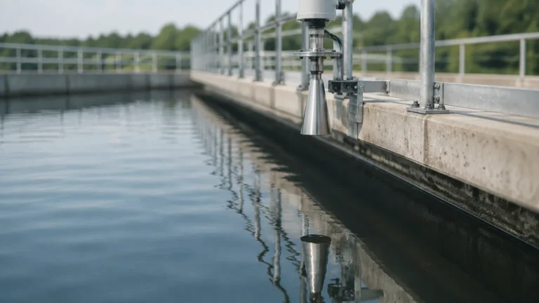
In the field of industrial process control, the MR240 stands as a sophisticated solution for non-contact level measurement. Specifically designed as a high-frequency radar level transmitter, the MR240 utilizes 26GHz microwave technology to provide precision in environments where traditional contact-based sensors or lower-frequency alternatives often fail. As part of the Welk portfolio of industrial instruments, this model is engineered to address the complexities of liquid and solid level monitoring in industries ranging from chemical processing to wastewater management.
Selecting the correct instrumentation requires a deep understanding of both the technology and the specific application requirements. For engineers looking to integrate these systems into broader automation frameworks, the Main Page of the Welk technical catalog offers a comprehensive starting point for reviewing compatible hardware and support documentation.
Measurement Principle: 26GHz High-Frequency Radar
The MR240 operates on the principle of Time Domain Reflectometry (TDR) or, more commonly in this specific model class, the Time of Flight (ToF) principle. The instrument emits high-frequency microwave pulses at 26GHz from its antenna. These pulses travel at the speed of light through the medium above the product (typically air or a gas blanket).
When the radar pulse encounters the surface of the medium being measured, a portion of the energy is reflected back toward the sensor. This reflection is caused by the change in the dielectric constant (εr) between the gas phase and the liquid or solid phase. The MR240's internal electronics measure the precise time interval between the emission of the pulse and the reception of the echo.
The distance ($D$) from the sensor reference point to the product surface is calculated using the formula:
$D = (c \times t) / 2$
Where:
* $c$ is the speed of light.
* $t$ is the measured travel time of the pulse.
Because the speed of light is a known constant, the accuracy of the MR240 is primarily dependent on the precision of its internal clock and its ability to distinguish the true surface echo from background noise or internal tank obstructions. The 26GHz frequency is particularly advantageous because it allows for a narrower beam angle and smaller antenna sizes compared to 6GHz or 10GHz models, which significantly reduces the risk of interference from tank walls or internal structures like agitators and heating coils.
Technical Specifications and Selection Criteria
When evaluating the MR240 for a specific project, engineers must consider the technical boundaries of the device. The following table outlines the standard performance parameters typically associated with this model class.
MR240 Performance Overview
| Parameter | Specification (Metric) | Specification (Imperial) |
| :— | :— | :— |
| Measuring Range | Up to 30 meters | Up to 98.4 feet |
| Accuracy | ±3 mm | ±0.11 inches |
| Frequency Range | 26 GHz | 26 GHz |
| Process Temperature | -40°C to +250°C | -40°F to +482°F |
| Process Pressure | -0.1 to 4.0 MPa | Vacuum to 580 PSI |
| Beam Angle | 8° to 20° (Antenna dependent) | 8° to 20° |
| Signal Output | 4-20mA / HART / RS485 | 4-20mA / HART / RS485 |
| Dielectric Constant | εr ≥ 1.9 | εr ≥ 1.9 |
Why Choose MR240 Over Other Technologies?
1. Vs. Ultrasonic Sensors: Unlike ultrasonic waves, radar pulses are not affected by vacuum, high pressure, or variations in gas composition and temperature. The MR240 is therefore superior in tanks where steam, dust, or heavy vapors are present.
2. Vs. Guided Wave Radar (GWR): While GWR is excellent for low-dielectric fluids, the MR240 is non-contact. This makes it ideal for corrosive or hygienic applications where the sensor should not touch the medium, reducing maintenance and contamination risks.
3. Vs. Hydrostatic Pressure: The MR240 measures the actual surface position regardless of changes in fluid density, making it more reliable for processes where the product concentration or temperature fluctuates significantly.
Installation Engineering and Best Practices
Correct installation is the most critical factor in ensuring the long-term reliability of the MR240. Even the most advanced radar signal processing cannot compensate for a poorly positioned sensor.
Position and Orientation
To avoid false echoes, the MR240 should be installed at a distance from the tank wall that is at least 1/6th of the tank diameter. It must never be installed directly in the center of a domed tank, as this can create a "focal point" effect where multiple reflections converge at the sensor, leading to signal saturation or ghost echoes.
The Blind Zone (Dead Zone)
Every radar sensor has a minimum distance it can measure, known as the blind zone or dead zone. For the MR240, this is typically the first 0.2m to 0.4m (200mm to 400mm) from the antenna tip. If the liquid level rises into this zone, the sensor will lose the ability to track the surface accurately. Engineers should select a nozzle height or mounting bracket that ensures the maximum high-level alarm point remains below this blind zone.
Nozzle Considerations
The nozzle on which the MR240 is mounted should be as short and wide as possible. If the nozzle is too long or narrow, the radar waves will reflect off the interior of the nozzle before reaching the tank, creating a large "initial echo" that can mask the true surface level when the tank is nearly full. For optimal results, the antenna should extend slightly beyond the bottom of the nozzle.
Avoiding Obstructions
Internal obstructions such as ladders, pipes, and agitators will reflect radar energy. The MR240 includes "False Echo Suppression" software, which allows the user to map out these static reflections. However, it is best practice to install the unit in a location where the signal beam path is clear of such obstacles. If an agitator is present, the sensor should be mounted in a position where the beam does not hit the blades at a 90-degree angle.
Application-Specific Considerations
Corrosive Environments
In chemical storage applications involving acids or bases, the MR240 can be equipped with a PTFE (Teflon) or PFA flange cover and antenna shield. This ensures that the metallic components of the sensor are not exposed to aggressive vapors. Because the measurement is non-contact, the lifespan of the instrument is significantly extended compared to contact-based probes.
Solid and Powder Measurement
While primarily used for liquids, the MR240 is also capable of measuring solids like plastic pellets or grain. However, solids often have a lower dielectric constant and do not form a flat surface (creating an "angle of repose"). In these cases, a gimbal or swiveling flange is recommended to align the antenna perpendicular to the slope of the material for maximum signal return.
High-Pressure and High-Temperature Tanks
For steam boilers or pressurized chemical reactors, the MR240 utilizes specialized glass seals or ceramic barriers. These components maintain the pressure integrity of the vessel while allowing the 26GHz signal to pass through with minimal attenuation.

Limitations and Operational Risks
While the MR240 is a robust instrument, it is not a universal solution. Engineers must be aware of the following limitations:
* Extremely Low Dielectric Media: Fluids with a dielectric constant below 1.9 (such as certain liquefied gases or ultra-pure oils) may not reflect enough energy for a reliable signal. In these instances, a stilling well or a Guided Wave Radar (GWR) might be required.
* Heavy Foam: Dense, thick foam can absorb radar pulses rather than reflecting them. If a process produces significant foam, the MR240 might report a "Loss of Echo" (LOE) error. Testing the specific foam density is recommended before final commissioning.
* Turbulence: Extreme surface turbulence can scatter the radar signal. While the MR240 uses sophisticated tracking algorithms to filter this noise, a stilling well is the preferred engineering solution for highly agitated tanks.
Frequently Asked Questions (FAQ)
Q: Does the MR240 require field calibration?
A: The MR240 is factory-calibrated. In the field, the user only needs to perform a "basic setup," which involves inputting the tank height (probe length), the 4mA point (bottom), and the 20mA point (top). No actual level changes are required for this configuration.
Q: Can the MR240 be used in hazardous areas?
A: Yes, the MR240 is typically available with Intrinsic Safety (Ex ia) or Explosion-Proof (Ex d) certifications, making it suitable for use in Zone 0, 1, and 2 environments common in the oil and gas industry.
Q: How does the MR240 handle build-up on the antenna?
A: The 26GHz signal is relatively resistant to thin layers of dust or condensation. However, heavy viscous build-up will attenuate the signal. For applications with heavy coating, a parabolic antenna or an air-purge system can be used to keep the antenna face clean.
Q: Is a special computer required for configuration?
A: Configuration can be performed via the integrated display and push-buttons, a HART handheld communicator, or a PC using DTM/FDT software. This flexibility allows for easy maintenance in both the workshop and the field.
Conclusion
The MR240 radar level meter is a high-performance instrument that provides reliable, non-contact measurement for a wide range of industrial applications. By leveraging 26GHz technology, it offers the precision and narrow beam focus necessary for modern process vessels. When integrated with proper installation techniques and an understanding of the medium's dielectric properties, the MR240 becomes an essential component of an accurate level control strategy.
For further technical details, wiring diagrams, and specific model variations, professionals are encouraged to review the Main Page to ensure the selected hardware aligns with their specific operational requirements and safety standards.