Gas Pressure Monitoring Device
Gas Pressure Monitoring Device
In industrial process control, a gas pressure monitoring device is a fundamental instrument used to measure, display, and transmit the force exerted by a gas within a piping system or a storage vessel. Whether managing compressed air lines, monitoring natural gas distribution, or ensuring the safety of pressurized chemical reactors, these devices provide the critical data necessary for operational efficiency and personnel safety. For engineers and facility managers, selecting the correct pressure instrumentation is as vital as choosing the right level measurement solutions found on the Main Page of industrial instrumentation catalogs.
Understanding Gas Pressure Measurement Principles
Before selecting a gas pressure monitoring device, it is essential to understand the physical principles that govern how these instruments interact with the process medium. Pressure is defined as the force exerted by a fluid (liquid or gas) per unit area ($P = F/A$). In gas applications, this measurement is typically categorized into three types:
1. Gauge Pressure: Measured relative to the local atmospheric pressure. This is the most common form of measurement for general industrial applications.
2. Absolute Pressure: Measured relative to a perfect vacuum. This is critical for processes where atmospheric pressure fluctuations would introduce unacceptable errors, such as in high-altitude operations or vacuum distillation.
3. Differential Pressure: The difference in pressure between two points. In gas systems, this is often used to monitor filter clogging or to calculate flow rates across an orifice plate.
Sensing Technologies
Modern electronic gas pressure monitoring devices utilize several primary sensing technologies to convert mechanical force into an electrical signal:
* Piezoresistive Strain Gauges: These sensors utilize the change in electrical resistance of a semiconductor (usually silicon) when it is subjected to mechanical stress. They are highly sensitive and widely used for general-purpose gas monitoring.
* Capacitive Sensors: These measure the change in electrical capacitance between a flexible diaphragm and a fixed metal plate. Capacitive sensors are known for their robustness and ability to withstand high overpressure conditions.
* Resonant Wire Sensors: These use a wire suspended in a diaphragm. As the diaphragm moves due to pressure, the tension in the wire changes, altering its resonant frequency. These are favored for high-precision applications.
Types of Gas Pressure Monitoring Devices
Gas pressure monitoring devices are categorized based on their output and functionality. Choosing the right category depends on whether the goal is simple local observation or integration into a Distributed Control System (DCS).
Pressure Gauges (Mechanical)
Mechanical gauges, such as those utilizing a Bourdon tube, provide a local visual readout without the need for external power. While they do not transmit data, they serve as essential secondary backups for safety verification.
Pressure Transmitters (Electronic)
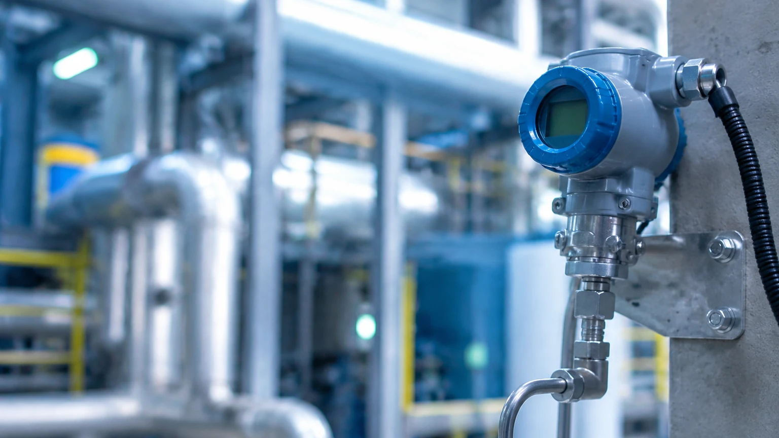
An electronic gas pressure monitoring device or transmitter converts the sensed pressure into a standardized signal, typically 4-20 mA, 0-10 V, or digital protocols like HART, Modbus, or PROFIBUS. These are the workhorses of industrial automation, allowing for remote monitoring and automated alarm triggering.
Pressure Switches
These devices do not provide a continuous measurement but are designed to open or close an electrical circuit when a specific pressure threshold is reached. They are used for emergency shutdowns or to cycle compressors on and off.
Technical Selection Criteria
Selecting a gas pressure monitoring device requires a thorough evaluation of the process conditions. The following table provides a general guide for comparing common sensor materials and their applications.
| Feature | Piezoresistive (Silicon) | Ceramic Capacitive | Metallic Diaphragm (SS316L) |
| :— | :— | :— | :— |
| Typical Accuracy | 0.1% to 0.25% FS | 0.2% to 0.5% FS | 0.075% to 0.2% FS |
| Pressure Range | 0.1 bar to 1000 bar | 0.1 bar to 60 bar | 0.01 bar to 400 bar |
| Chemical Resistance | Moderate (requires isolation) | High (corrosion resistant) | High (with coatings) |
| Temperature Stability | Moderate | High | Excellent |
| Best Use Case | General air/gas lines | Corrosive gas monitoring | High-precision process control |
When evaluating a device, engineers must confirm the following specifications:
* Full Scale (FS) Range: The device should ideally operate within 25% to 75% of its maximum range to ensure longevity and accuracy.
* Wetted Materials: The parts of the device in contact with the gas (diaphragms, seals, and fittings) must be chemically compatible with the gas. For example, sour gas (containing $H_2S$) requires NACE-compliant materials like Hastelloy C-276.
* Process Temperature: Gas temperatures can fluctuate significantly. Ensure the device has adequate temperature compensation or use cooling siphons for high-temperature steam or gas lines.
Integration with Level Measurement Systems
A gas pressure monitoring device is often an integral component of a comprehensive level measurement strategy. In pressurized storage tanks, such as those containing Liquefied Petroleum Gas (LPG) or pressurized chemicals, a standard hydrostatic level transmitter cannot accurately measure the liquid height alone.
In these "closed tank" scenarios, the total pressure at the bottom of the tank is the sum of the liquid's hydrostatic head and the gas pressure in the ullage space (the area above the liquid). To determine the true level, a differential pressure measurement is required. One side of the sensor measures the bottom pressure, while the other side is vented to the top of the tank to subtract the gas pressure. Alternatively, two separate transmitters—one for liquid and one gas pressure monitoring device—can be used, with the calculation performed in the PLC.
Installation Considerations and Best Practices
The performance of a gas pressure monitoring device is heavily dependent on proper installation. Incorrect mounting can lead to signal noise, premature failure, or inaccurate readings.
1. Orientation: For gas applications, the transmitter should ideally be mounted above the process tap. This allows any moisture or condensate in the impulse lines to drain back into the process pipe or tank, preventing blockages.
2. Impulse Piping: Use the shortest possible length of tubing between the process and the sensor to minimize lag time. For gas, 6 mm or 10 mm (1/4" or 3/8") stainless steel tubing is standard.
3. Isolation and Venting: Always install a block-and-bleed manifold. This allows the device to be isolated from the process for calibration or maintenance and permits the safe venting of trapped gas pressure.
4. Environmental Protection: While many industrial devices are rated IP66 or IP67, they should still be shielded from direct solar radiation in hot climates to prevent electronic drift caused by excessive heat.
Limitations and Common Risks
Despite their reliability, gas pressure monitoring devices face several operational challenges:
* Overpressure Events: Sudden pressure spikes (water hammer in liquid-gas mixtures or regulator failure) can deform the sensing diaphragm, leading to a permanent zero-shift or total sensor failure.
* Permeation: Small molecules like Hydrogen ($H_2$) can permeate through standard stainless steel diaphragms, eventually causing the internal filling fluid to bubble and the sensor to drift. Gold-plated diaphragms are often required for high-concentration hydrogen applications.
* Condensation: If the gas contains moisture and the ambient temperature drops below the dew point, liquid can collect in the sensor housing or impulse lines, leading to false pressure readings.
Maintenance and Calibration
To maintain the integrity of the gas pressure monitoring device, a regular maintenance schedule is required. This typically includes:
* Zero-Point Verification: Periodically venting the sensor to atmosphere to ensure it reads zero. Many modern smart transmitters allow for a "digital zero" adjustment via HART communication.
* Calibration Checks: Using a deadweight tester or a high-precision pressure calibrator to verify accuracy across the full range (typically at 0%, 25%, 50%, 75%, and 100% of span).
* Visual Inspection: Checking for signs of corrosion on the housing or leaks at the process connections.
Frequently Asked Questions (FAQ)
Q: Can I use a liquid pressure transmitter for gas pressure monitoring?
A: In many cases, yes, provided the wetted materials are compatible. However, the installation orientation is different. For liquids, the sensor is usually mounted below the tap; for gases, it should be above the tap.
Q: What is the difference between a 2-wire and 4-wire gas pressure monitoring device?
A: A 2-wire device uses the same pair of wires for both power and the 4-20 mA signal, making it more cost-effective to install. A 4-wire device has separate wires for power (often 110/220V AC or 24V DC) and the signal, which is usually required for devices with high power consumption, such as those with heated displays or complex communication modules.
Q: How often should a gas pressure monitoring device be calibrated?
A: For most industrial applications, an annual calibration is sufficient. However, in critical safety systems or highly corrosive environments, semi-annual or quarterly checks may be necessary to ensure compliance with safety standards like SIL (Safety Integrity Level).
Q: What is the impact of gas density on pressure measurement?
A: For static pressure measurement, gas density has a negligible effect. However, if the device is used for flow measurement (differential pressure), the gas density—which changes with temperature and pressure—must be compensated for to maintain accuracy.
Conclusion
A reliable gas pressure monitoring device is a cornerstone of modern industrial safety and process optimization. By understanding the underlying measurement principles, selecting materials suited to the chemical environment, and adhering to rigorous installation standards, engineers can ensure long-term accuracy and system stability. For those integrating these devices into broader automation frameworks, reviewing the full range of compatible sensors and transmitters on the Main Page is a recommended step in the procurement and design phase.