Radar Level Transmitter 3d Model
Radar Level Transmitter 3D Model: Engineering Integration and Selection Guide
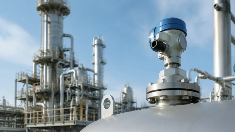
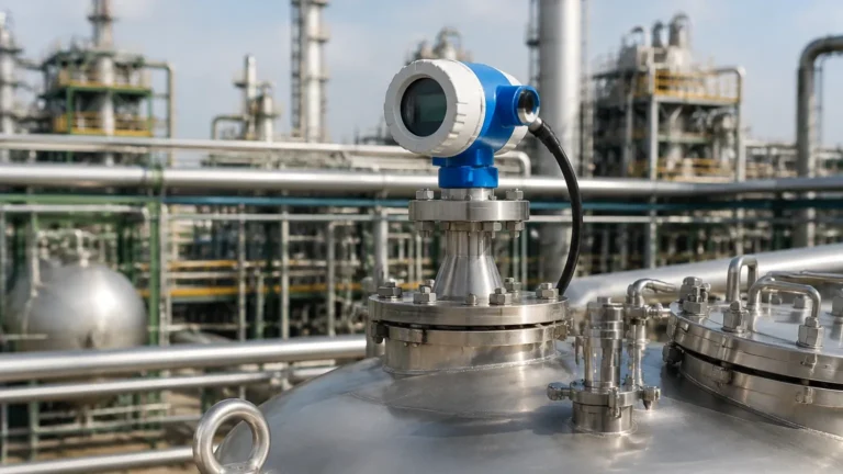
In modern industrial plant design, the transition from two-dimensional drafting to complex 3D modeling and Digital Twin integration has revolutionized how instrumentation is specified and installed. A radar level transmitter 3D model is no longer just a visual placeholder in a CAD drawing; it is a critical engineering asset used for spatial coordination, interference analysis, and maintenance planning. For engineers and procurement specialists, understanding the physical dimensions and the electromagnetic behavior represented by these models is essential for ensuring the reliability of Radar Level Meters in challenging process environments.
This guide explores the technical principles of radar level measurement, the role of 3D modeling in system integration, and the practical considerations necessary for selecting and installing these instruments in industrial applications.
Understanding the Measurement Principles
Before integrating a radar level transmitter into a 3D plant layout, it is vital to understand the underlying technology, as the physical design of the instrument—and thus its 3D model—is dictated by its operating frequency and antenna type.
Time of Flight (ToF) and Pulse Radar
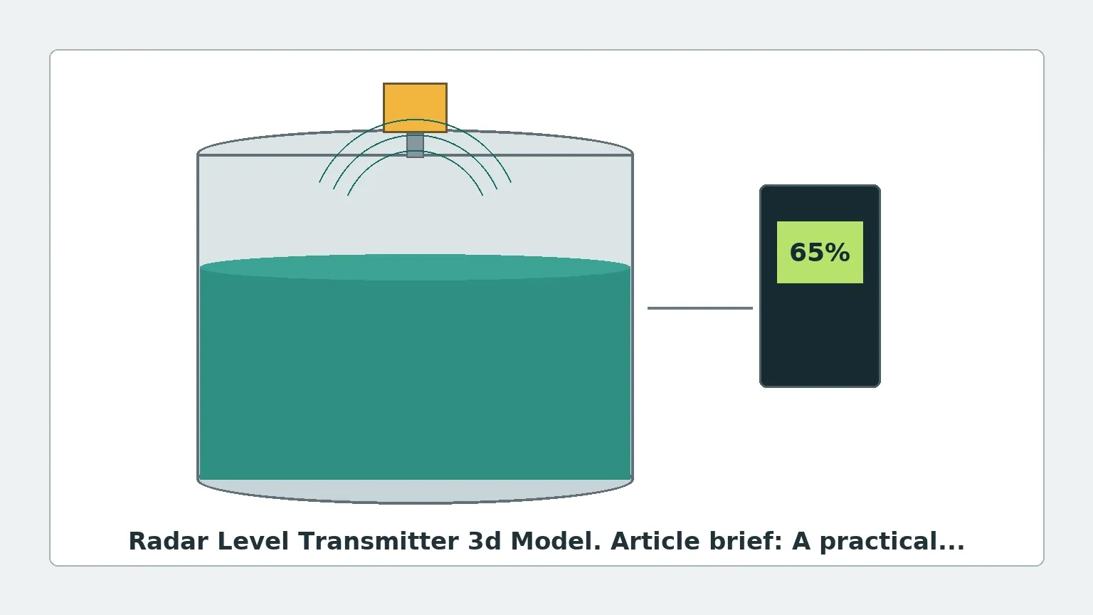
Pulse radar transmitters emit high-frequency microwave pulses toward the surface of the medium. The instrument measures the time it takes for the pulse to travel to the surface and reflect back to the sensor. Since the speed of light is constant, the distance is calculated as:
\[ Distance = \frac{C \times t}{2} \]
Where *C* is the speed of light and *t* is the transit time. Pulse radar is often used for simpler applications where extreme precision is not the primary requirement.
Frequency Modulated Continuous Wave (FMCW)
FMCW technology is the gold standard for high-precision industrial level measurement. Instead of pulses, the transmitter emits a continuous signal with a constantly changing frequency. The reflection from the product surface is received, and the frequency difference between the emitted and received signal is measured. This frequency shift is directly proportional to the distance. FMCW radar, particularly those operating at 80 GHz, offers a much narrower beam angle and higher resolution, which significantly impacts how the unit is modeled in a 3D environment.
The Role of the Radar Level Transmitter 3D Model in Engineering
When designing a chemical reactor, a storage tank, or a water treatment basin, the 3D model of the radar transmitter serves several technical functions beyond mere aesthetics.
1. Collision Detection and Spatial Coordination
In dense piping environments, space is at a premium. A 3D model (typically provided in STEP, IGES, or Revit formats) allows piping engineers to ensure that the transmitter head does not interfere with overhead walkways, structural steel, or adjacent piping. It also ensures that there is sufficient "swing room" for technicians to unscrew the housing cover or orient the display for local viewing.
2. Beam Angle Visualization and Interference Analysis
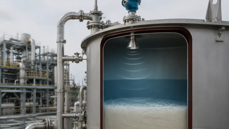
One of the most critical aspects of radar installation is the "keep-out zone." Radar signals propagate in a conical shape. If this cone intersects with internal tank structures—such as agitators, heating coils, ladders, or baffles—it creates false echoes (parasitic reflections) that can lead to measurement errors.
By using a radar level transmitter 3d model within CAD software, engineers can project a 3D cone representing the beam angle (e.g., 3°, 8°, or 10°) from the antenna face. This allows for the proactive identification of obstructions before the tank is even fabricated.
3. Nozzle Design Optimization
The 3D model helps determine the optimal nozzle height and diameter. If a nozzle is too long or too narrow, the radar signal may reflect off the internal weld seams of the nozzle itself, creating a "ringing" effect that obscures the true level in the upper portion of the tank (the blind zone).
Technical Selection Criteria
Selecting the right radar level meter requires balancing process conditions with the physical constraints identified during the 3D modeling phase.
| Feature | 6 GHz Radar | 26 GHz Radar | 80 GHz Radar |
| :— | :— | :— | :— |
| Beam Angle | Wide (approx. 20-30°) | Medium (approx. 8-12°) | Narrow (approx. 3-6°) |
| Accuracy | ±10 mm | ±2 mm to ±5 mm | ±1 mm |
| Antenna Size | Large (Horn/Rod) | Medium | Small (Lens/Flush) |
| Suitability | Heavy steam, turbulence | General process tanks | Narrow tanks, solids, high precision |
| Dielectric Constant | Requires εr > 2.0 | Requires εr > 1.6 | Requires εr > 1.4 |
Frequency Selection
* 80 GHz: Best for most modern applications. The small antenna size results in a compact 3D footprint, and the narrow beam avoids internal obstructions easily.
* 26 GHz: A versatile mid-range frequency suitable for many liquid applications where the tank geometry is relatively simple.
* 6 GHz: Used primarily in applications with heavy steam or foam, as the longer wavelength can penetrate surface disturbances more effectively, though the large antenna requires a significant 3D clearance.
Installation Considerations and Constraints
Proper installation is the difference between a reliable instrument and constant maintenance headaches. The following guidelines should be reflected in any 3D layout planning:
1. Avoid the Center: Never install a radar transmitter in the exact center of a cylindrical tank. This is where multiple reflections converge, and where a vortex typically forms during filling/emptying, both of which can confuse the sensor.
2. Distance from Wall: The sensor should ideally be installed at a distance of 1/6th of the tank diameter from the wall. This avoids interference from wall-mounted sensors or weld seams while staying clear of the center.
3. Nozzle Clearance: The antenna must extend past the bottom of the mounting nozzle. If the antenna is recessed inside the nozzle, the signal will bounce within the pipe, creating a large "dead zone" at the top of the measurement range.
4. Agitator Interference: If an agitator is present, the 3D model should be used to ensure the radar beam is directed at a portion of the liquid surface that remains relatively flat, avoiding the turbulent area near the shaft.
Limitations and Application Risks
While radar is one of the most robust level measurement technologies, it is not infallible. Engineers must account for the following risks:
* Low Dielectric Media: Materials with a low dielectric constant (εr), such as liquid nitrogen or certain hydrocarbons, reflect very little microwave energy. In these cases, a guided wave radar (GWR) or a high-sensitivity 80 GHz FMCW unit is required.
* Heavy Foam: Dense, thick foam can absorb the radar signal entirely. If the foam is light and airy, the radar may see through it to the liquid; if it is conductive and dense, the radar may trigger off the top of the foam.
* Condensation and Buildup: In chemical processes, vapors can condense on the antenna. While modern lens antennas (common in 80 GHz models) are designed to shed droplets, heavy buildup of solids can eventually attenuate the signal.
Frequently Asked Questions (FAQ)
Q: Can I use a radar level transmitter 3D model for BIM (Building Information Modeling)?
A: Yes. Most manufacturers, including Welk, provide high-fidelity 3D models that can be imported into BIM software like Revit or AutoCAD Plant 3D. This ensures that the instrument is included in the project's digital twin for lifecycle management.
Q: How does the dielectric constant affect the 3D model selection?
A: The dielectric constant doesn't change the physical 3D model of the exterior, but it dictates the *type* of antenna needed. For low εr fluids, you might need a larger horn antenna or a parabolic dish to capture more reflected energy, which significantly changes the spatial requirements in your 3D design.
Q: What is the "Blind Zone"?
A: The blind zone (or blocking distance) is the area directly beneath the antenna where the instrument cannot measure. This is usually between 50 mm and 300 mm depending on the frequency and antenna design. This must be accounted for in the 3D model to ensure the tank's maximum fill level does not enter this zone.
Q: Is 80 GHz always better than 26 GHz?
A: Not necessarily. While 80 GHz offers better precision and a narrower beam, 26 GHz or 6 GHz may be more cost-effective for large, open-air basins or tanks where steam and dust are extremely heavy, as the lower frequencies are less affected by atmospheric particles.
Summary for International Buyers
When sourcing radar level transmitters for global projects, it is essential to request the following documentation from the manufacturer:
1. Dimensional Drawings and 3D Files: Ensure the radar level transmitter 3d model matches the specific process connection (Flange, Threaded, or Clamp) required for your region (e.g., DN vs. ANSI flanges).
2. Certification: Verify that the equipment meets local hazardous area requirements (ATEX, IECEx, or UL/CSA).
3. Material Traceability: For chemical and food industries, ensure the wetted parts (PTFE, 316L Stainless Steel) are certified for the specific media.
By integrating accurate 3D models early in the design phase and following rigorous selection criteria, engineers can minimize installation errors and maximize the operational lifespan of their level measurement systems. For a comprehensive range of industrial solutions, professionals often turn to specialized manufacturers to Review product options and application support tailored to their specific environmental challenges.