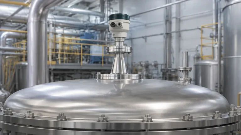
Fmcw Radar Level Transmitter
FMCW Radar Level Transmitter: Engineering Principles and Selection Guide
In the landscape of industrial process control, accurate level measurement is critical for inventory management, process safety, and operational efficiency. Among the various technologies available, the fmcw radar level transmitter has emerged as a preferred solution for complex applications where contact-based measurement or simple ultrasonic sensors fail.
Modern Radar Level Meters utilize Frequency Modulated Continuous Wave (FMCW) technology to provide high-precision, non-contact measurement across a wide range of media, including liquids, slurries, and solids. This guide provides a technical overview of FMCW principles, selection criteria, and practical installation considerations for engineering professionals.
1. Understanding the FMCW Measurement Principle
To specify the correct instrument, it is essential to understand how FMCW differs from traditional pulse-based radar. While both use electromagnetic waves, their methods of determining distance are fundamentally different.
Frequency Modulation and the Beat Signal
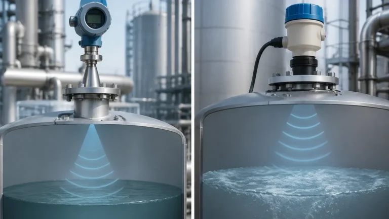
Unlike pulse radar, which transmits a short burst of energy and measures the "Time of Flight" (ToF) until the echo returns, an FMCW radar level transmitter emits a continuous signal. This signal is not at a fixed frequency; instead, it is modulated over a specific bandwidth (e.g., from 76 GHz to 81 GHz) following a linear ramp, often referred to as a "sweep."
As the transmitted signal travels to the product surface and reflects back, the transmitter continues to sweep the frequency. By the time the echo reaches the receiver, the frequency of the transmitted signal has changed. The instrument compares the frequency of the received echo with the frequency of the signal currently being transmitted.
This difference in frequency ($Δf$) is directly proportional to the time delay ($Δt$), which in turn is proportional to the distance ($D$). The relationship can be simplified as:
$$D = \frac{c \cdot \Delta f}{2 \cdot (df/dt)}$$
Where:
* c is the speed of light.
* df/dt is the rate of frequency change (the slope of the ramp).
Why FMCW Offers Superior Accuracy
Because FMCW technology measures frequency shifts rather than extremely short time intervals, it can achieve much higher resolution. In pulse radar, measuring a few millimeters of change requires timing electronics capable of resolving picoseconds. In FMCW, a few millimeters of change results in a measurable frequency shift, allowing for standard accuracies of ±1 mm (0.04 in) to ±2 mm (0.08 in).
2. Technical Comparison: FMCW vs. Pulse Radar
| Feature | Pulse Radar | FMCW Radar |
| :— | :— | :— |
| Signal Type | Short bursts (pulses) | Continuous wave with frequency sweep |
| Measurement Variable | Time delay (Time of Flight) | Frequency difference (Δf) |
| Signal-to-Noise Ratio | Moderate | High (better echo separation) |
| Accuracy | Typical ±5 mm to ±10 mm | Typical ±1 mm to ±2 mm |
| Energy Density | Low peak power | High average power |
| Application Suitability | Simple liquid storage | Complex processes, solids, and high-precision needs |
3. Frequency Bands: 26 GHz vs. 80 GHz
The frequency at which an fmcw radar level transmitter operates significantly impacts its performance, particularly regarding beam angle and signal focus.
26 GHz (K-Band)
26 GHz transmitters are versatile and widely used for liquid measurement in medium-sized tanks. They offer a balance between signal penetration and focus. However, they typically have wider beam angles (8° to 20°), which may cause interference if the tank has internal obstructions like agitators or heating coils.
80 GHz (W-Band)
80 GHz technology represents the current state-of-the-art in radar level measurement. The higher frequency allows for a much narrower beam angle (as low as 3°).
* Narrow Focus: A 3° beam can easily avoid internal obstructions and tank walls, making it ideal for tall, narrow silos or vessels with complex internals.
* Better Reflection: Higher frequencies reflect better off low-dielectric media and uneven surfaces (such as slanted solid piles).
* Smaller Antennas: High-frequency units can use smaller process connections (e.g., 1-inch NPT) while maintaining a focused beam.
4. Key Selection Criteria for Industrial Applications
When selecting a radar level meter, engineers must evaluate several environmental and media-specific factors to ensure long-term reliability.
Dielectric Constant (εr)
The dielectric constant of the material being measured is the most critical factor in radar performance.
* High εr (>10): Materials like water or acids reflect signals strongly.
* Low εr (1.4 to 4): Materials like oils, hydrocarbons, or plastic pellets reflect weakly. FMCW is often required for low εr materials because its high signal-to-noise ratio can extract weak echoes from background noise.
Process Conditions
* Temperature: Standard units operate up to 80°C (176°F). For high-temperature applications (e.g., molten glass or steam boilers), specialized horn antennas with cooling fins or ceramic seals can handle up to 1,000°C (1,832°F).
* Pressure: Standard flanges handle up to 40 bar (580 psi), but high-pressure versions are available for up to 160 bar (2,320 psi).
* Vapor and Dust: While radar is generally unaffected by dust, heavy steam or extremely dense dust clouds can attenuate the signal. 80 GHz FMCW is particularly effective at penetrating dust in grain or cement silos.
Antenna Types
* Horn Antenna: The standard for most applications. Large horns provide better focus.
* Lens Antenna: Flush-mounted designs that are resistant to condensation and buildup. Often made of PTFE or PEEK.
* Drop Antenna: Designed specifically for corrosive environments or where heavy buildup is expected; the shape allows droplets to run off the surface.
5. Installation Guidelines and Constraints
Even the most advanced fmcw radar level transmitter will perform poorly if installed incorrectly. Follow these engineering best practices:
1. Avoid the Center: Do not mount the transmitter in the exact center of a domed tank. This can cause multiple reflections that amplify noise. The ideal position is usually 1/3 of the tank radius from the wall.
2. Nozzle Height: The antenna should ideally extend past the mounting nozzle. If the nozzle is long and narrow, it can create "ringing" or internal reflections that mask the true level. If a long nozzle is unavoidable, an 80 GHz unit with a narrow beam is required.
3. Obstruction Clearance: Ensure the signal beam path is clear of ladders, pipes, and agitator blades. If an obstruction is present, the transmitter's "false echo suppression" software must be used to map out the static interference.
4. Angle of Incidence: For liquid applications, the transmitter must be mounted perpendicular to the surface. For solids, an aiming flange (swivel mount) may be necessary to align the beam with the material's angle of repose.
6. Practical Selection Table
| Application | Recommended Frequency | Antenna Type | Consideration |
| :— | :— | :— | :— |
| Water Treatment (Open Channel) | 26 GHz or 80 GHz | Plastic Encapsulated | Corrosion resistance |
| Chemical Storage (Aggressive) | 80 GHz | PTFE Lens | Flush mount to avoid corrosion |
| Cement/Grain Silos | 80 GHz | Horn with Dust Shield | High signal strength for dust |
| Small Process Vessel (<2m) | 80 GHz | Small Threaded | Narrow beam for tight spaces |
| High-Temp Oil/Bitumen | 26 GHz | Horn with Cooling Fins | Thermal isolation for electronics |
7. Limitations and Application Risks
While highly versatile, FMCW radar is not a universal solution for every process. Engineers should be aware of the following risks:
* Heavy Foam: Dense, thick foam (like shaving cream) can absorb the radar signal entirely, leading to a "loss of echo" error. If foam is constant, a guided wave radar (GWR) or ultrasonic sensor may be more appropriate, depending on the foam density.
* Extremely Low Dielectric Media: Liquefied gases (e.g., Nitrogen) have dielectric constants very close to 1.0. These require specialized high-sensitivity FMCW units or guided wave radar with a coaxial probe.
* Turbulence: Extreme surface turbulence can scatter the signal. While FMCW software can filter some of this noise, a stilling well may be required for highly agitated liquids.
8. Frequently Asked Questions (FAQ)
Q: Does the FMCW radar need to be calibrated for different media?
A: No. Unlike capacitive sensors, radar measures distance based on the speed of light. It does not need to be recalibrated if you change the liquid in the tank, provided the dielectric constant is above the instrument's minimum threshold.
Q: Can FMCW radar measure through a plastic tank roof?
A: Yes. If the tank is made of non-conductive material like PE, PP, or GRP, the radar can be mounted outside the tank and measure through the roof. Note that this will cause some signal attenuation.
Q: What is the "Dead Zone"?
A: The dead zone (or blocking distance) is the area immediately below the antenna where the transmitter cannot accurately measure. For most FMCW units, this is between 50 mm and 200 mm. It is important to mount the unit high enough to avoid the maximum fill level entering this zone.
Q: How does 80 GHz handle condensation?
A: High-frequency units are more sensitive to water droplets on the lens. However, most modern 80 GHz transmitters use convex lens designs that encourage droplets to migrate to the edges, minimizing signal interference.
Conclusion
The fmcw radar level transmitter represents a significant leap in industrial measurement capability. By providing millimeter-level accuracy and the ability to ignore complex internal tank geometries, it has become the standard for modern process automation. When selecting a unit, engineers should prioritize the frequency (80 GHz for focus, 26 GHz for general use), antenna material compatibility, and the dielectric properties of the media. For more information on specific models and technical support, Review product options and application support.