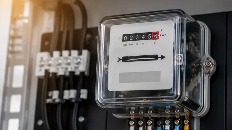
Sigrist Turbidity Meters
Sigrist Turbidity Meters
In industrial process control and water quality management, turbidity measurement serves as a primary indicator of liquid clarity and the presence of suspended solids. Sigrist turbidity meters are widely recognized in the B2B sector for their precision and reliability, particularly in demanding applications such as drinking water treatment, beverage production, and chemical processing. This guide provides a technical overview of turbidity measurement principles, the specific advantages of Sigrist technology, and practical considerations for integrating these instruments into broader industrial automation systems.
Understanding Turbidity Measurement Principles
Before selecting a specific instrument, it is essential to understand the physics of how turbidity is measured. Turbidity is not a direct measurement of the quantity of suspended particles, but rather an optical property: the expression of the optical interference caused by particles that scatter and absorb light rather than transmit it in a straight line.
The Nephelometric Principle (90° Scattering)
The most common method for measuring low to medium turbidity is nephelometry. According to international standards such as ISO 7027, a light beam is directed into the sample, and a detector is positioned at 90 degrees to the light source. When the light hits suspended particles, it scatters. The intensity of the light reaching the 90° detector is proportional to the concentration of particles. This method is highly sensitive and is the standard for monitoring drinking water quality, where turbidity levels are typically below 1 NTU (Nephelometric Turbidity Unit).
Absorption and Forward Scattering
For high-turbidity applications, such as sludge monitoring or concentrated chemical processes, the 90° method becomes less effective because the light cannot penetrate the dense sample. In these cases, instruments may use:
- Absorption (180°): Measuring the loss of light intensity as it passes through the sample.
- Forward Scattering (15-25°): Measuring light scattered at a narrow angle, which is better for detecting larger particles or high concentrations.
Sigrist turbidity meters often utilize a dual-beam or multi-angle approach to compensate for color interference and light source aging, ensuring long-term stability without frequent recalibration.
Key Features of Sigrist Turbidity Meters
Sigrist-Photometer has historically focused on eliminating the common failure points of optical sensors. Their design philosophy centers on "non-contact" measurement and optical compensation.
Non-Contact Measurement
A significant challenge in turbidity sensing is the fouling of the optical windows. When a sensor is submerged in a process fluid, biofilms, minerals, or oils can accumulate on the glass, leading to measurement drift. Sigrist addresses this through "falling stream" technology. In this configuration, the sample fluid passes through the instrument in a free-falling stream, and the optical measurement is taken through the air. Since the fluid never touches the optical windows, maintenance requirements are drastically reduced, and the risk of window fouling is eliminated.
Dual-Beam Optical System
To maintain accuracy, Sigrist instruments often employ a dual-beam system. This involves splitting the light source into a measurement beam and a reference beam. By comparing the two, the electronics can automatically compensate for changes in the light source intensity or the sensitivity of the detectors. This results in an instrument that remains accurate over years of operation.
Evaluation Criteria for Industrial Turbidity Sensors
When evaluating sigrist turbidity meters or alternative solutions, engineers must consider the specific requirements of their process. The following criteria are fundamental to a successful installation:
1. Measuring Range: Ensure the instrument can cover the full range of expected turbidity, from the lowest baseline to the highest peak during process upsets. Ranges are typically measured in NTU, FNU (Formazin Nephelometric Units), or EBC (European Brewery Convention).
2. Process Temperature and Pressure: Standard sensors may be limited to 50°C or 60°C. For high-temperature CIP (Clean-in-Place) cycles or high-pressure chemical lines, specialized housings and seals are required.
3. Chemical Compatibility: The wetted parts of the flow cell or sensor body must be resistant to the process fluid. Common materials include stainless steel (316L), PVC, or PVDF.
4. Integration Capabilities: Modern industrial plants require digital communication. Look for instruments that support 4-20 mA with HART, Modbus TCP/IP, or Profibus.
Technical Selection Table
| Application | Typical Range | Recommended Principle | Key Consideration |
| :— | :— | :— | :— |
| Drinking Water | 0 – 1 NTU | 90° Nephelometry | High sensitivity, low drift |
| Wastewater Effluent | 0 – 100 NTU | 90° or Dual-angle | Resistance to fouling |
| Phase Separation | 100 – 4000 NTU | Absorption / 180° | Fast response time |
| Filtration Monitoring | 0 – 10 NTU | 90° Nephelometry | Detection of filter breakthroughs |
| Cooling Water | 0 – 50 NTU | 90° Nephelometry | Corrosion resistance |
Installation Guidelines and Best Practices
The performance of a turbidity meter is heavily dependent on how it is installed. Even the most expensive Sigrist turbidity meters will provide inaccurate data if the installation environment is poorly managed.
Managing Air Bubbles
Air bubbles are the primary enemy of optical turbidity measurement. A bubble scatters light just like a solid particle, leading to false high readings. To mitigate this:
- Install the sensor in a pressurized line where bubbles are kept in solution.
- Use an integrated de-aeration or "bubble trap" chamber before the measurement point.
- Avoid installing sensors at the highest point of a pipe loop where air naturally collects.
Flow Rate Control
For bypass-style meters like the Sigrist AquaScat, the flow rate must be maintained within a specific range (e.g., 1 to 5 liters per minute). If the flow is too slow, particles may settle in the flow cell; if it is too fast, turbulence may create micro-bubbles.
Orientation and Location
- Vertical Upward Flow: In-line sensors should ideally be installed in a vertical pipe with upward flow. This ensures the pipe is always full and helps prevent air pockets.
- Ambient Light: Ensure the measurement chamber is light-tight. External ambient light entering the sensor can interfere with the sensitive photodetectors.
Common Risks and Limitations in Turbidity Monitoring
While Sigrist turbidity meters are robust, users should be aware of the following limitations:
* Color Interference: Some fluids have a natural color that absorbs light at the same wavelength used by the sensor. Using a near-infrared (NIR) light source (860 nm) according to ISO 7027 helps minimize this effect.
* Particle Size and Shape: Turbidity is not a mass concentration. Two samples with the same mass of solids but different particle sizes will yield different NTU values. Calibration should always be performed against a known standard like Formazin.
* Condensation: In cold water applications, condensation can form on the outside of the optical windows if the electronics housing is not properly sealed or desiccated. Sigrist often uses heated optics or dry air purging to prevent this.
Synergies with Level Measurement Systems
In integrated industrial automation, turbidity measurement rarely exists in isolation. It is frequently paired with level measurement technologies to provide a complete picture of tank or vessel status. For instance, in a sedimentation tank, a radar level meter or ultrasonic level sensor is used to monitor the liquid surface, while a turbidity meter monitors the clarity of the effluent.
Reliable level measurement ensures that the turbidity sensor always has a sufficient head of fluid and that pumps do not run dry. For comprehensive process control, engineers often source these instruments together to ensure compatibility with the central PLC or SCADA system. To explore a wide range of industrial level measurement options that complement turbidity monitoring, you can Review product options and application support on the Welk Main Page.
Frequently Asked Questions
Q: How often do Sigrist turbidity meters need calibration?
A: Due to the dual-beam optical design and non-contact measurement, Sigrist meters are exceptionally stable. While many regulations require a calibration check every 3 to 6 months, the actual drift is often negligible over a year. It is recommended to use a secondary solid standard for quick routine checks.
Q: Can these meters be used in hazardous areas?
A: Yes, specific models are available with ATEX or IECEx certifications for use in explosive atmospheres, which is common in the oil and gas or chemical industries.
Q: What is the difference between NTU and FNU?
A: Both units are numerically equivalent when measuring Formazin. NTU (Nephelometric Turbidity Units) is the term typically used under US EPA 180.1 (using white light), while FNU (Formazin Nephelometric Units) is used under ISO 7027 (using infrared light).
Q: How do I handle very high pressure in the process line?
A: For high-pressure applications, a bypass system with a pressure-reducing valve is often the best approach. This allows the sensitive optical instrument to operate at atmospheric pressure while still sampling the high-pressure process stream.
By following these engineering guidelines and understanding the underlying optical principles, B2B procurement and technical teams can ensure that their investment in Sigrist turbidity meters provides the long-term accuracy and low maintenance required for modern industrial operations.