Electricity Flow Meter
Electricity Flow Meter
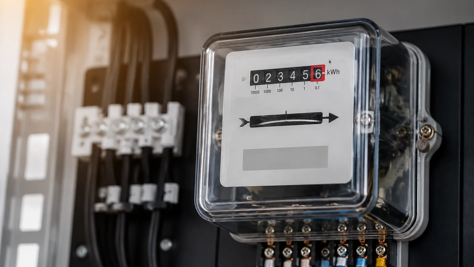
In the landscape of industrial automation and process control, the term "electricity flow meter" typically refers to instruments designed to measure the rate and volume of electrical energy consumption within a system. While traditional flow meters measure the movement of liquids or gases through a pipe, an electricity flow meter—more formally known as an industrial energy meter or power analyzer—monitors the flow of electrons to provide data on power usage, efficiency, and system health.
For engineers and facility managers, understanding the energy footprint of process equipment is as critical as monitoring the physical contents of a tank. In many integrated systems, electricity flow meters work in tandem with level measurement instruments to ensure that pumps, mixers, and heaters are operating within their design parameters. This guide explores the principles of electrical measurement, its practical applications, and how it integrates with broader process monitoring solutions.
Measurement Principles of Electrical Flow
To effectively select and implement an electricity flow meter, one must first understand the fundamental physical principles that govern electrical measurement. Unlike fluid dynamics, which rely on pressure and velocity, electrical flow is measured through the interaction of voltage, current, and time.
Current Sensing (Amperage)
Most industrial electricity flow meters utilize Current Transformers (CTs) or Rogowski coils to measure the flow of current without breaking the circuit.
- Current Transformers (CTs): These operate on the principle of electromagnetic induction. As alternating current (AC) flows through a primary conductor, it induces a proportional current in the secondary winding of the CT, which the meter then interprets.
- Shunt Resistors: In direct current (DC) applications, a shunt resistor of a known, very low resistance is placed in series with the load. The voltage drop across the resistor is measured and converted to a current reading using Ohm’s Law ($I = V/R$).
Voltage and Power Factor
Voltage is measured by connecting the meter in parallel with the load. However, in AC systems, simply multiplying voltage by current does not always yield the true power consumption. The "Power Factor"—the ratio of real power (kW) to apparent power (kVA)—must be accounted for. An electricity flow meter calculates this by analyzing the phase angle between the voltage and current waveforms. This is particularly important in industrial environments where inductive loads, such as large pump motors used alongside level sensors, can cause significant phase shifts.
Energy Calculation
Total energy consumption is the integral of power over time, typically expressed in kilowatt-hours (kWh). Advanced meters also capture "demand," which is the average power used over a specific interval (e.g., 15 minutes), helping facilities avoid peak demand charges from utilities.
The Relationship Between Electrical and Fluid Flow
In B2B industrial contexts, there is often a direct correlation between electrical flow and fluid flow. When a pump moves a liquid into a storage tank, the electricity flow meter monitors the energy consumed by the motor, while a level meter monitors the resulting change in volume.
If a radar level meter indicates that a tank level is rising slower than expected while the electricity flow meter shows the pump is drawing maximum current, it suggests a mechanical issue, such as a clogged filter or a failing impeller. By cross-referencing data from the Main Page of a process control dashboard, engineers can perform predictive maintenance and optimize the "wire-to-water" efficiency of their systems.
Key Evaluation Criteria for Selection
Selecting the right electricity flow meter requires a detailed assessment of the electrical environment and the data requirements of the project. The following table provides a comparison of common industrial metering technologies:
| Feature | Basic Sub-meter | Advanced Power Quality Analyzer | Wireless Energy Sensor |
| :— | :— | :— | :— |
| Primary Use | Tenant billing / Basic monitoring | Troubleshooting / Harmonic analysis | Retrofitting / Remote monitoring |
| Measurement | kWh, Volts, Amps | THD, Transients, Sags/Swells | kWh, Real-time Amperage |
| Accuracy Class | 1.0 or 0.5 | 0.2s | 1.0 |
| Communication | Modbus RTU / Pulse | Ethernet/IP, BACnet, MQTT | LoRaWAN, Zigbee, Wi-Fi |
| Installation | DIN Rail | Panel Mount | Clamp-on / Split-core |
Accuracy and Standards
In the United States and Europe, meters are often rated by "Accuracy Class" (e.g., ANSI C12.20 or IEC 62053-22). A Class 0.5 meter has an allowable error of 0.5%. For revenue-grade billing, high accuracy is mandatory, whereas for internal process optimization, a Class 1.0 meter is usually sufficient.
Communication Protocols
Modern industrial meters must integrate with SCADA or Building Management Systems (BMS). Common protocols include:
- Modbus RTU/TCP: The industry standard for simplicity and reliability.
- BACnet: Primarily used in building automation and HVAC systems.
- EtherNet/IP: Preferred in high-speed manufacturing environments using Allen-Bradley or similar PLCs.
Installation Considerations and Best Practices
Proper installation is paramount to ensuring both the safety of personnel and the accuracy of the data collected by an electricity flow meter.
1. Current Transformer Orientation: CTs are directional. Installing a CT backward will result in negative power readings or incorrect energy accumulation. Most CTs feature an arrow indicating the direction of the load.
2. Voltage Taps and Fusing: Voltage sense leads should always be protected by fuses or circuit breakers located as close to the tap point as possible to prevent fire hazards in the event of a short circuit.
3. Phase Matching: It is critical to ensure that the voltage lead for Phase A is matched with the CT for Phase A. Mismatched phases will lead to wildly inaccurate power factor and wattage calculations.
4. Signal Interference: In environments with high electromagnetic interference (EMI)—common near Variable Frequency Drives (VFDs)—shielded twisted-pair cabling should be used for communication lines, and the meter itself should be properly grounded.
Limitations of Electricity Flow Meters
While highly versatile, these instruments have specific limitations that must be acknowledged during the design phase:
- Harmonic Distortion: Non-linear loads (like VFDs and LED lighting) create harmonics that can distort waveforms. Basic meters may provide inaccurate readings in these environments; a "True RMS" meter is required.
- Minimum Current Thresholds: Most CT-based meters have a "starting current" or a minimum threshold (often 0.5% to 1% of the CT's rated capacity). Below this level, the meter may not register any flow, leading to under-reporting of standby power.
- Environmental Constraints: Standard meters are often designed for indoor use within electrical panels. For outdoor or wash-down environments, they must be housed in NEMA 4X or IP66-rated enclosures.
Practical Application: Pump System Optimization
In water treatment and chemical processing, electricity flow meters are frequently paired with level measurement technologies. Consider a scenario involving a deep well pump. By monitoring the electrical flow (power consumption) alongside the hydrostatic level of the well, operators can calculate the "Specific Energy" (kWh per cubic meter of water pumped).
An increase in specific energy over time is a leading indicator of pump wear or well screen clogging. This data-driven approach allows for scheduled maintenance before a catastrophic failure occurs, significantly reducing downtime and operational costs. For those exploring integrated sensor suites, reviewing the Main Page of specialized instrument providers can offer insights into how level and flow data are aggregated in modern industrial IoT (IIoT) platforms.
Frequently Asked Questions (FAQs)
Q: Can an electricity flow meter measure both AC and DC?
A: Most industrial meters are designed specifically for either AC or DC. While some high-end power analyzers can handle both, it is standard practice to select a meter dedicated to the specific power type of the application.
Q: What is the difference between a split-core and a solid-core CT?
A: Solid-core CTs require the conductor to be disconnected and threaded through the ring, offering higher accuracy. Split-core CTs can be opened and clamped around an existing wire, making them ideal for retrofitting without shutting down the system.
Q: How often should an electricity flow meter be calibrated?
A: For internal monitoring, a calibration check every 3 to 5 years is typical. For billing applications, local regulations may require annual or biennial certification by a licensed laboratory.
Q: Does an electricity flow meter measure water flow?
A: No. An electricity flow meter measures electrical energy. However, the term is sometimes confused with an "electromagnetic flow meter" (magmeter), which uses magnetic fields to measure the flow of conductive liquids in a pipe. It is vital to clarify the measurement objective (energy vs. fluid) during the procurement process.
Conclusion
Integrating an electricity flow meter into an industrial process provides a window into the efficiency and health of the system that physical sensors alone cannot offer. By understanding the principles of voltage, current, and power factor, and by selecting instruments that meet the specific accuracy and communication needs of the facility, engineers can build more resilient and cost-effective operations. When combined with accurate level measurement, these tools form the backbone of a modern, data-centric industrial strategy.