Rtd Thermowell
Rtd Thermowell
In industrial process control, the accuracy of temperature measurement is as critical as the durability of the instruments used. The RTD thermowell assembly represents the standard solution for protecting sensitive temperature elements from the harsh realities of high-pressure, corrosive, and high-velocity process environments. While Resistance Temperature Detectors (RTDs) provide the precision required for modern automation, the thermowell provides the mechanical integrity necessary to maintain a sealed system.
For engineers managing complex systems—ranging from chemical reactors to water treatment facilities—understanding the synergy between the RTD and its protective housing is essential. This guide explores the principles, selection criteria, and installation best practices for the RTD thermowell, with a specific focus on its role in supporting broader instrumentation goals, including accurate level measurement.
Understanding RTD and Thermowell Principles
To appreciate the value of an RTD thermowell, one must first understand the individual components and how they interact within a process loop.
The RTD Mechanism
An RTD (Resistance Temperature Detector) operates on the principle that the electrical resistance of a metal changes in a predictable manner as temperature fluctuates. Most industrial RTDs utilize platinum (Pt) because of its stability and linear resistance-to-temperature relationship. The most common types are Pt100 (100 ohms at 0°C) and Pt1000 (1000 ohms at 0°C).
RTDs are preferred over thermocouples in applications requiring high accuracy and repeatability over a range typically spanning -200°C to 650°C (-328°F to 1202°F). However, the RTD element itself is fragile; it consists of fine wire or a thin film that cannot withstand direct exposure to turbulent fluids or abrasive media.
The Thermowell Function
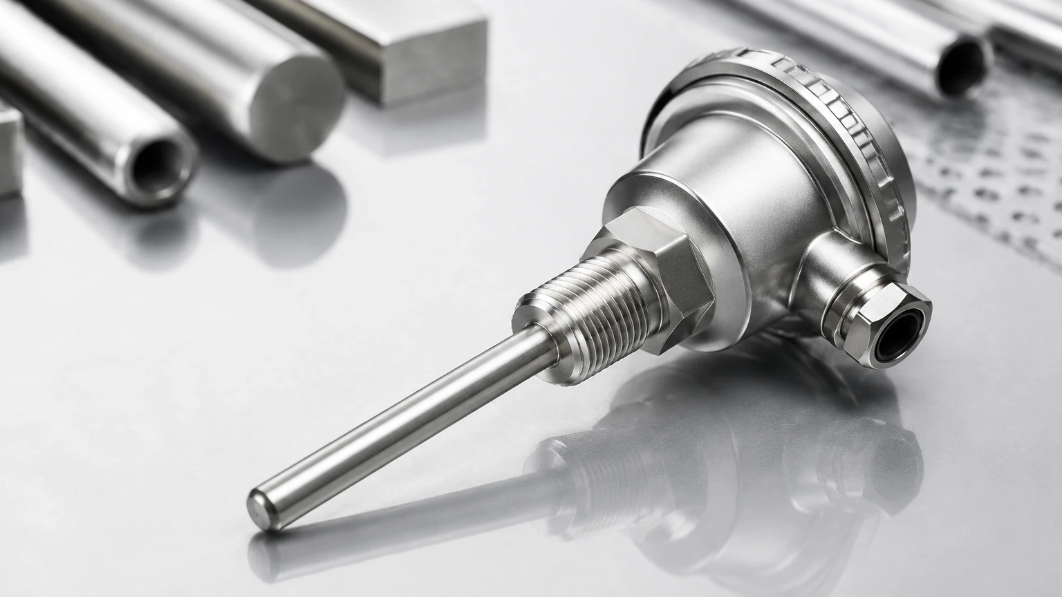
A thermowell is a cylindrical pressure-tight fitting used to protect temperature sensors installed in industrial processes. It acts as a barrier between the process media and the sensing element. Beyond protection, the primary advantage of a thermowell is that it allows for the removal and replacement of the RTD without breaking the process seal or draining the vessel. This is a critical feature for continuous industrial operations where downtime must be minimized.
Why Use a Thermowell with an RTD?
The integration of an RTD into a thermowell is driven by three primary engineering requirements:
1. Pressure Containment: In high-pressure pipelines or tanks, the thermowell serves as a structural component capable of withstanding the full process pressure, ensuring the RTD is not crushed or compromised.
2. Chemical Compatibility: While an RTD might be made of platinum, its lead wires and sheath might not be compatible with aggressive acids or bases. Thermowells can be machined from a wide variety of corrosion-resistant alloys.
3. Mechanical Protection: High-velocity flows can cause physical damage or induce vibrations. A properly designed thermowell provides the necessary rigidity to prevent the sensor from snapping or failing due to fatigue.
Key Selection Criteria for Industrial RTD Thermowells
Selecting the correct RTD thermowell requires a balance between thermal response time and mechanical strength. A thicker wall provides more protection but slows down the heat transfer to the RTD, leading to measurement lag.
Material Selection
The material must be compatible with the process fluid. Common materials include:
* 316/316L Stainless Steel: The standard for water treatment and general chemical applications.
* Hastelloy C-276: Used for highly corrosive environments involving chlorides or acids.
* Monel 400: Ideal for sea water and hydrofluoric acid applications.
* Inconel 600: Preferred for high-temperature oxidation resistance.
Shank Construction
* Straight: The diameter is uniform throughout the insertion length. These are easy to manufacture and suitable for low-velocity applications.
* Stepped: The diameter decreases at the tip. This reduces the mass around the sensor, improving response time while maintaining strength at the base.
* Tapered: The diameter gradually decreases from the base to the tip. This design offers the best strength-to-weight ratio and is the standard for high-velocity flow applications.
Connection Types
How the thermowell attaches to the process is determined by safety standards and maintenance frequency.
| Connection Type | Best For | Advantages | Limitations |
| :— | :— | :— | :— |
| Threaded | Low-pressure, non-hazardous | Low cost, easy installation | Potential for leaks over time |
| Flanged | High-pressure, corrosive media | High structural integrity, easy to clean | Higher cost, requires gaskets |
| Socket Weld | Permanent installations | Leak-proof, high-pressure rated | Difficult to remove for replacement |
| Weld-in | Critical high-pressure systems | Maximum safety and seal | Cannot be removed without cutting |
Installation and Engineering Considerations
Correct installation is paramount to ensuring that the RTD thermowell provides an accurate representation of the process temperature.
Insertion Length (U-Length)
The "U-length" refers to the distance from the bottom of the connection to the tip of the thermowell. For accurate measurement, the tip must be positioned in the active flow of the process. A general rule of thumb is that the insertion length should be at least 10 times the diameter of the thermowell tip to minimize heat conduction errors through the wall of the vessel.
Lagging Extension (T-Length)
In insulated pipes or vessels, a lagging extension is required. This is an extra length of the thermowell hex or neck that extends beyond the insulation, allowing the connection head to remain accessible and preventing the electronics from overheating.
Wake Frequency Calculations
In flowing media, a thermowell acts as a cantilevered beam. As fluid passes over it, vortices are shed on alternating sides (Karman Vortex Street). If the frequency of this vortex shedding matches the natural frequency of the thermowell, resonance occurs, which can lead to catastrophic mechanical failure. Engineers must perform wake frequency calculations according to ASME PTC 19.3 TW to ensure the design is safe for the specific flow velocity, density, and pressure of the application.
Temperature Compensation in Level Measurement
While this guide focuses on the RTD thermowell, it is important to note its role in broader industrial automation, particularly in level measurement. Many level technologies are temperature-dependent. For instance, when using ultrasonic level sensors, the speed of sound varies with air temperature. Without an accurate temperature reading—often provided by an RTD assembly—the level calculation will drift.
Similarly, in hydrostatic level measurement, the sensor measures the pressure exerted by a liquid column. Since the density of a liquid changes with temperature, a precise temperature input is required to convert pressure into an accurate height or volume reading. In these scenarios, the RTD thermowell is often mounted in close proximity to the level transmitter to provide real-time compensation data. For those seeking comprehensive measurement arrays, you can Review product options and application support to see how integrated temperature and level solutions are implemented in the field.
Common Risks and Maintenance Guidelines
Despite their robust design, RTD thermowell assemblies are subject to several failure modes:
* Response Lag: If there is an air gap between the RTD probe and the inner wall of the thermowell, the response time will be significantly delayed. Using a spring-loaded RTD ensures the sensor tip makes constant contact with the bottom of the thermowell, optimizing heat transfer.
* Erosion: In slurries or high-velocity particulate flows, the thermowell wall can thin over time. Regular ultrasonic thickness testing or visual inspections during shutdowns are recommended.
* Corrosion: Even "corrosion-resistant" materials can fail if the process chemistry changes. Stress corrosion cracking is a particular risk in high-pressure stainless steel applications.
Maintenance Checklist
1. Visual Inspection: Check for signs of pitting, erosion, or bending on the thermowell stem.
2. Calibration: Periodically remove the RTD from the thermowell and check it against a known standard (e.g., a dry block calibrator).
3. Seal Integrity: Inspect gaskets on flanged connections and thread sealant on threaded connections for leaks.
Frequently Asked Questions (FAQ)
Q: How does a thermowell affect the accuracy of an RTD?
A: A thermowell does not inherently change the accuracy of the RTD, but it introduces a "thermal lag." This means the RTD will take longer to reach the actual process temperature if the temperature is changing rapidly. For steady-state processes, the impact on accuracy is negligible if the insertion depth is sufficient.
Q: What is the standard insertion depth for a pipe?
A: For pipes, the tip of the thermowell should ideally be located in the center third of the pipe diameter. In small pipes (less than 100 mm or 4 inches), the thermowell is often installed at an elbow or inclined against the flow to achieve sufficient immersion.
Q: Can I use a thermowell in a vacuum?
A: Yes, but the connection must be vacuum-rated (typically flanged or welded). Additionally, heat transfer in a vacuum relies more on radiation and conduction through the thermowell wall, so ensuring the RTD is in physical contact with the thermowell tip is even more critical.
Q: When should I choose a tapered thermowell over a straight one?
A: Tapered thermowells should be chosen whenever the process involves high flow velocities (typically above 3 m/s for liquids or 15 m/s for gases). The tapered shape increases the natural frequency of the well, making it less susceptible to flow-induced vibration.
Conclusion
The RTD thermowell is a foundational component in industrial process monitoring. By providing a robust barrier against the environment while allowing for precise temperature sensing, it ensures both the safety of the facility and the accuracy of the data. Whether used for standalone temperature monitoring or as a compensation tool for advanced level measurement systems, proper selection of material, geometry, and installation method is vital. For engineers and procurement specialists, prioritizing the mechanical integrity of the thermowell is the first step toward a reliable and low-maintenance instrumentation loop. For further technical specifications and to explore a full range of industrial measurement instruments, visit the Welk Main Page for expert guidance and product support.