Mensor
Mensor
In the field of industrial automation, the term "mensor" is fundamentally linked to the science of mensuration—the precise measurement of physical dimensions, including height, volume, and pressure. For process engineers and facility managers, selecting the right instrumentation for level measurement is not merely a matter of hardware acquisition; it is an exercise in ensuring operational safety, inventory accuracy, and process efficiency.
Welk, a professional manufacturer of industrial level measurement instruments, provides a comprehensive suite of solutions designed to meet the rigorous demands of modern industry. Whether the application involves aggressive chemicals, high-pressure oil and gas storage, or municipal water treatment, understanding the underlying principles of measurement is the first step toward a successful installation. This guide explores the diverse technologies used in industrial level mensuration, providing the technical framework necessary for informed decision-making.
Principles of Industrial Level Measurement
Level measurement technologies are generally categorized into two types: contact and non-contact. The choice between these depends on the physical properties of the medium, the container's geometry, and the environmental conditions of the site.
Hydrostatic Pressure (Contact)
Hydrostatic level measurement relies on the principle that the pressure at a specific point in a static liquid is proportional to the height of the liquid column above it. The formula used is $P = \rho \cdot g \cdot h$, where $P$ is pressure, $\rho$ is the density of the liquid, $g$ is the gravitational constant, and $h$ is the height. By using a high-precision pressure transmitter, often referred to in technical circles as a mensor-grade sensor due to its accuracy requirements, the system can calculate the exact level based on the weight of the fluid.
Time-of-Flight (Non-Contact)
Both radar and ultrasonic level meters utilize the Time-of-Flight (ToF) principle. The instrument emits a signal (electromagnetic waves for radar, sound waves for ultrasonic) that travels to the surface of the material, reflects, and returns to the sensor. The distance is calculated using the formula $D = (c \cdot t) / 2$, where $c$ is the speed of the wave in the medium and $t$ is the measured time. These technologies are preferred when the sensor must remain isolated from the process media.
Electromechanical and Magnetic (Contact)
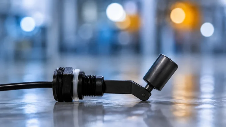
Magnetic level gauges and level switches use physical interaction. A float containing a magnet moves with the liquid level, triggering external reed switches or flipping magnetic flaps to provide a visual and electronic indication. These are highly valued for their reliability in high-pressure environments where electronic components might be at risk.
Hydrostatic Level Transmitters: Precision Pressure Mensuration
Hydrostatic transmitters are a staple in water treatment and deep-well monitoring. Because they measure the weight of the liquid, they are inherently effective for calculating volume in tanks with consistent density.
Welk’s hydrostatic solutions utilize high-stability silicon or ceramic diaphragms. When the liquid level rises, the increased pressure deforms the diaphragm, which is then converted into a 4-20mA or digital signal.
Key Considerations for Hydrostatic Sensors:
* Vented Cables: To compensate for changes in atmospheric pressure, submersible transmitters use a vented cable. This ensures the sensor measures only the liquid's weight, not the air pressure pushing down on the surface.
* Density Sensitivity: If the liquid density changes significantly (e.g., due to temperature fluctuations or mixing of different chemicals), the level reading will drift. In such cases, dual-sensor differential pressure (DP) systems or temperature compensation algorithms are required.
Radar Level Meters: The Standard for High-Precision Mensuration
Radar technology has become the preferred choice for complex industrial applications. Modern radar level meters operate at high frequencies, such as 26GHz or 80GHz. The higher the frequency, the shorter the wavelength, which results in a narrower beam angle and better focus.
In B2B environments like chemical processing or oil storage, the ability to avoid internal tank obstructions (like agitators or heating coils) is critical. 80GHz radar, in particular, offers a level of precision that aligns with the highest "mensor" standards, providing accuracy within ±1mm.
Advantages of Radar
1. Media Independence: Radar waves are largely unaffected by changes in pressure, temperature, or the presence of vapors and dust.
2. Low Maintenance: With no moving parts and no contact with the media, radar sensors have an exceptionally long service life.
3. Versatility: Suitable for both liquids and solids (powders, grains, and aggregates).
To explore the full range of high-frequency radar and other measurement technologies, engineers can refer to the Main Page for detailed product specifications.
Ultrasonic Level Sensors: Cost-Effective Non-Contact Solutions
Ultrasonic sensors are widely used in water and wastewater applications, such as open channel flow measurement and sump level monitoring. They provide a balance between performance and cost-effectiveness.
However, because ultrasonic waves travel through the air, they are sensitive to the air's composition. Temperature changes significantly affect the speed of sound; therefore, Welk ultrasonic sensors include integrated temperature probes to provide real-time compensation.
Limitations to Watch For:
* Vacuum Conditions: Sound waves cannot travel in a vacuum, making ultrasonic sensors unsuitable for vacuum tanks.
* Heavy Foam: Thick foam can absorb the ultrasonic signal, leading to a "loss of echo" error.
* Extreme Dust: While some dust is manageable, heavy particulate matter in the air can scatter sound waves.

Technical Selection Table
Choosing the correct instrument requires a comparison of technical specifications against application requirements. The following table provides a general guideline for selecting between Welk’s primary technologies.
| Technology | Typical Accuracy | Max Range | Media Type | Key Limitation |
| :— | :— | :— | :— | :— |
| Radar (80GHz) | ±1 mm | 120m | Liquids / Solids | High initial cost |
| Ultrasonic | ±0.25% of range | 30m | Liquids / Slurries | Sensitive to foam/vapor |
| Hydrostatic | ±0.1% to 0.5% | 200m+ | Clean Liquids | Density must be constant |
| Magnetic Gauge | ±5 mm | 6m+ | Liquids | Contact-based; moving parts |
| Level Switch | N/A (Point level) | N/A | Liquids / Solids | No continuous output |
Installation and Engineering Considerations
Proper installation is as important as the sensor technology itself. Even a mensor-grade high-precision instrument will fail to provide accurate data if installed incorrectly.
1. Blocking Distance (Dead Zone)
All ToF sensors (radar and ultrasonic) have a "dead zone" directly beneath the sensor face where measurements cannot be taken. For ultrasonic sensors, this is typically 0.25m to 0.5m. When designing a tank, the sensor must be mounted high enough so that the maximum liquid level never enters this zone.
2. Beam Angle and Obstructions
The beam angle determines the "footprint" of the signal at the bottom of the tank. If the beam hits a ladder, a pipe, or an agitator blade, it will create a false echo.
* 80GHz Radar: Offers a beam angle as narrow as 3°, allowing for installation in very small nozzles or tall, narrow silos.
* Ultrasonic: Typically has a wider beam (around 10°), requiring more clearance from tank walls.
3. Mounting Position
Sensors should never be mounted in the center of a tank (which can cause multiple reflections) or directly above the fill stream (which creates turbulence and signal noise). The ideal position is usually 1/3 of the radius from the tank wall.
Limitations and Common Risks in Level Mensuration
Every technology has its boundaries. Ignoring these can lead to process failure or safety hazards.
* Dielectric Constant ($ε_r$): Radar relies on the dielectric constant of the material to reflect the signal. Materials with very low $ε_r$ (like some oils or liquefied gases) reflect poorly. In these cases, a Guided Wave Radar (GWR) or a high-sensitivity non-contact radar is required.
* Turbulence: Rapidly mixing liquids or surface waves can scatter signals. Using a stilling well or a bypass pipe can stabilize the surface for the sensor.
* Build-up: In sticky or viscous applications, material can build up on the sensor face. While radar can often "see through" thin layers of build-up, ultrasonic and hydrostatic sensors are more likely to fail under these conditions.
Frequently Asked Questions (FAQ)
Q: How do I choose between a 26GHz and an 80GHz radar?
A: 26GHz radar is excellent for general liquid applications and is very cost-effective. 80GHz radar should be chosen for solids, applications with narrow nozzles, or when the highest possible precision (±1mm) is required.
Q: Can hydrostatic sensors be used in pressurized tanks?
A: A standard submersible hydrostatic sensor cannot be used in a pressurized tank because it cannot distinguish between liquid pressure and head pressure. For pressurized vessels, a Differential Pressure (DP) transmitter is used, measuring pressure at both the bottom and the top of the tank.
Q: What is the maintenance schedule for these instruments?
A: Non-contact sensors like radar and ultrasonic typically require only an annual visual inspection. Hydrostatic sensors in wastewater may require periodic cleaning of the diaphragm to prevent sludge build-up from affecting accuracy.
Q: Is it possible to measure level in a tank with heavy agitation?
A: Yes. The best approach is to use a radar level meter with a stilling well. The stilling well acts as a vertical pipe that protects the liquid surface from waves, providing a calm area for the radar to measure.
For more technical resources, installation checklists, and to review product options and application support, please visit our Main Page. Welk remains committed to providing reliable, accurate, and cost-effective level measurement solutions for industrial automation worldwide.