Solid Flow Meter
Solid Flow Meter
In the landscape of industrial process automation, the accurate measurement of bulk solids is significantly more complex than measuring liquid or gas flow. A solid flow meter is a specialized instrument designed to quantify the mass flow rate of dry particulate solids, such as powders, granules, pellets, or crushed minerals, as they move through a production line. Whether for inventory control, batching, or process optimization, selecting the correct measurement technology is essential for maintaining product quality and operational efficiency.
Industrial facilities in sectors like cement production, food processing, chemical manufacturing, and mining rely on these instruments to ensure that the material balance is maintained. Unlike liquid flow, which is typically continuous and uniform, solid flow is often characterized by variations in particle size, bulk density, and moisture content, all of which can influence the accuracy of the measurement. This guide explores the fundamental principles, selection criteria, and installation requirements for modern solid flow measurement systems.
Measurement Principles of Solid Flow Meters
Before selecting a solid flow meter, it is crucial to understand the physics behind the various measurement technologies. Most industrial systems fall into one of four categories: mechanical impact, microwave/radar, Coriolis, or gravimetric.
Impact Plate Principle
Impact flow meters are among the most common mechanical solutions for measuring the flow of bulk solids in gravity-fed systems. The principle is based on the conversion of kinetic energy into a measurable force. As material falls from a fixed height onto a sensing plate inclined at a specific angle (usually 30 to 45 degrees), the horizontal component of the impact force is measured by a load cell or a linear variable differential transformer (LVDT).
Because the meter only measures the horizontal force, it is relatively immune to the effects of material buildup on the plate, provided the buildup does not interfere with the plate's movement. The mass flow rate is calculated based on the relationship between the impact force and the velocity of the material.
Microwave and Radar Technology
Non-contact solid flow meters often utilize microwave or radar technology. These sensors are typically mounted on pipes or chutes. The sensor emits a high-frequency electromagnetic field. When solid particles move through this field, they reflect the signals back to the sensor. By analyzing the frequency shift (Doppler effect) and the amplitude of the reflected signal, the system can determine both the velocity of the particles and the concentration of the material in the stream.
This method is particularly effective for pneumatic conveying systems where material is moved by air pressure. Since there are no moving parts in the flow stream, these meters are highly resistant to wear and require minimal maintenance.
Coriolis Mass Flow
For high-precision applications, the Coriolis principle is applied to solids. The material is fed onto a rotating centrifugal wheel. As the particles move from the center to the outer edge of the wheel, they are accelerated. This acceleration creates a torque on the drive motor that is directly proportional to the mass flow rate. Coriolis solid flow meters offer high accuracy (often within ±0.5%) and are independent of material density or particle size variations.
Radiometric (Nuclear) Measurement
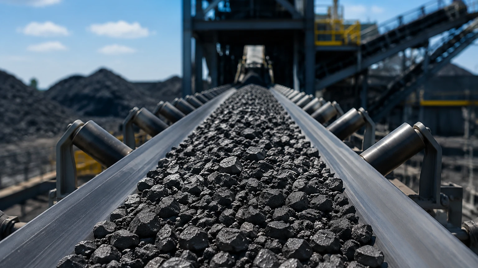
Radiometric flow meters use a gamma radiation source and a detector placed on opposite sides of a conveyor belt or pipe. The amount of radiation reaching the detector is inversely proportional to the mass of the material passing through the beam. When combined with a speed sensor (for belt applications), the system calculates the mass flow rate. This is a non-intrusive method ideal for highly abrasive or toxic materials, though it requires strict regulatory compliance regarding radioactive sources.
Key Evaluation Criteria for Selection
Choosing the right solid flow meter requires a detailed analysis of the material properties and the installation environment. Engineers should confirm the following parameters before procurement:
1. Material Characteristics: Particle size distribution, bulk density, and abrasiveness are the primary factors. For example, large, abrasive rocks in a mining application would destroy a delicate impact plate but might be suitable for a heavy-duty belt scale or radiometric system.
2. Flow Range: It is essential to define the minimum and maximum flow rates (typically measured in kg/h or t/h). Most meters have a specific "turn-down ratio" where they maintain accuracy.
3. Moisture Content: High moisture can cause materials to stick to sensing elements or change the dielectric constant, which affects microwave sensors. If moisture levels fluctuate significantly, a Coriolis or gravimetric system may be more reliable.
4. Process Temperature and Pressure: Standard sensors may fail in high-temperature kilns or high-pressure pneumatic lines. Specialized housings and cooling systems may be required.
For a broader view of how flow measurement integrates with overall tank and silo management, including level detection, professionals can consult the Main Page of industrial instrumentation providers for integrated solution architectures.
Comparison of Solid Flow Measurement Technologies
| Technology | Typical Accuracy | Primary Application | Advantages | Limitations |
| :— | :— | :— | :— | :— |
| Impact Plate | ±1% to ±3% | Gravity chutes, vertical flow | Low cost, simple mechanical design | Sensitive to velocity changes |
| Microwave | ±3% to ±5% | Pneumatic conveying, dust | Non-intrusive, no wear | Requires stable moisture levels |
| Coriolis | ±0.5% | High-precision batching | Extremely accurate, density independent | High initial cost, mechanical complexity |
| Radiometric | ±1% to ±2% | Abrasive/Hazardous materials | Non-contact, high durability | Regulatory requirements for radiation |
| Belt Scale | ±0.5% to ±2% | Conveyor belts | Handles high volumes, robust | Requires regular mechanical calibration |
Installation and Engineering Considerations
Proper installation is often more critical to accuracy than the choice of the sensor itself. For solid flow meters, the geometry of the inlet and outlet sections must be carefully managed to ensure a stable flow profile.
Chute Design and Material Velocity
For impact meters, the material must fall from a consistent height to ensure constant velocity at the point of impact. If the fall height varies, the kinetic energy will change, leading to inaccurate readings. Engineers often install a "dead box" or a curved baffle above the meter to normalize the material speed and direction.
Vibration and Noise Interference
Mechanical meters, particularly those using load cells, are sensitive to structural vibrations. In cement plants or crushing facilities, heavy machinery can create significant "noise" in the weight signal. Use of flexible couplings, vibration-dampening mounts, and electronic filtering in the transmitter is necessary to isolate the flow signal.
Grounding and Static Electricity
Dry powders moving at high speeds often generate significant static electricity. This can interfere with the electronics of microwave sensors or cause material to cling to the walls of the measurement device. Proper electrical grounding of the pipework and the sensor housing is a mandatory safety and functional requirement.
Limitations and Common Risks
Despite advancements in technology, solid flow measurement has inherent limitations that must be addressed during the design phase:
* Abrasive Wear: In high-velocity systems, particles act like sandpaper. Impact plates and internal linings must be made of hardened materials like tungsten carbide or ceramic to prevent thinning, which would change the calibration of the instrument.
* Material Coating: Fine powders, especially those with any moisture or oil content, tend to coat the internal surfaces of the meter. This can dampen the movement of mechanical parts or attenuate the signals of non-contact sensors.
* Calibration Challenges: Unlike liquid meters that can be calibrated with water, solid flow meters require the actual process material for calibration. This often involves a "catch-and-weigh" procedure, where material is diverted into a hopper on load cells to verify the meter’s accuracy in real-time.
Integration with Level Measurement Systems
In many B2B industrial applications, a solid flow meter is used in conjunction with level measurement instruments. While the flow meter tracks the rate of material entering or leaving a silo, level sensors (such as 80GHz radar or ultrasonic transmitters) provide the absolute volume of inventory. This dual-verification approach allows for "mass balance" calculations, which are vital for detecting leaks, identifying blockages, or preventing silo overfills.
For instance, if a flow meter indicates that 50 tons of material have been added to a silo, but the radar level meter shows no change in the material surface, operators can immediately identify an upstream diversion or a sensor failure. For detailed technical specifications on radar and ultrasonic level sensors that complement solid flow systems, engineers can visit the Main Page to review compatible hardware.
Frequently Asked Questions (FAQ)
Q: How often should a solid flow meter be calibrated?
A: This depends on the abrasiveness of the material and the criticality of the process. For high-precision batching, monthly verification is recommended. For general inventory monitoring, an annual calibration is usually sufficient, provided there is no significant wear on the sensing elements.
Q: Can a solid flow meter handle different materials on the same line?
A: Most meters are calibrated for a specific material density and particle size. If the material changes (e.g., switching from sand to gravel), the meter will likely require a new calibration curve or a different scaling factor in the transmitter.
Q: What is the minimum flow required for a microwave sensor?
A: Microwave sensors generally require a minimum particle concentration to generate a reliable reflection. They are not suitable for extremely sparse flows where the air-to-solid ratio is very high, such as in some light dust extraction systems.
Q: Do impact plates work with sticky materials?
A: Generally, no. Sticky materials will adhere to the plate, increasing its tare weight and dampening the impact force, which leads to significant measurement errors. For sticky solids, a non-contact radiometric meter or a belt scale is a better alternative.
Q: What is the typical pipe diameter for pneumatic solid flow meters?
A: Most microwave-based solid flow meters are designed for standard pipe sizes ranging from 10 mm to 300 mm. Larger pipes may require multiple sensors to ensure the entire cross-section of the flow is monitored.