Vera Magnetic Flow Meter
Vera Magnetic Flow Meter
In the landscape of industrial process control, the accurate measurement of liquid flow is as critical as monitoring tank levels. The Vera magnetic flow meter represents a standard in electromagnetic flow measurement, designed to handle conductive liquids with high precision and reliability. While many facilities focus heavily on level instrumentation, such as those found on our Main Page, integrating robust flow data is essential for mass balance, chemical dosing, and overall system efficiency.
This guide provides a comprehensive technical overview of the Vera magnetic flow meter, detailing its operating principles, selection criteria, installation requirements, and common industrial applications. By understanding the engineering behind these devices, project managers and engineers can ensure long-term performance in demanding environments.
Understanding the Operating Principle of Magnetic Flow Meters
The Vera magnetic flow meter operates based on Faraday’s Law of Electromagnetic Induction. This principle states that a conductor moving through a magnetic field produces an electrical signal within the conductor, which is directly proportional to the velocity of the moving conductor.
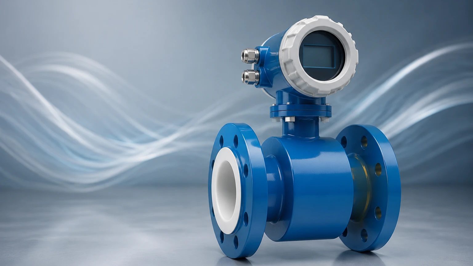
In the context of a flow meter, the "conductor" is the process liquid itself. For the meter to function, the liquid must have a minimum level of electrical conductivity (typically >5 μS/cm). The device consists of a non-magnetic tube lined with an insulating material. Two electromagnetic coils are placed outside or within the flow tube to generate a constant magnetic field (B) across the cross-section of the pipe.
As the conductive liquid flows through this magnetic field at a certain velocity (v), an electromotive force (E) is induced. This voltage is picked up by two electrodes mounted flush against the pipe wall. The mathematical relationship is expressed as:
E = B × v × d
Where:
* E is the induced voltage.
* B is the magnetic field strength.
* v is the average velocity of the liquid.
* d is the distance between the electrodes (inner diameter of the pipe).
Because the magnetic field strength and the distance between electrodes are constant, the induced voltage is directly proportional to the flow velocity. The transmitter then converts this microvolt-level signal into a standard industrial output, such as a 4-20mA signal, pulse, or digital communication protocol (HART, Modbus, Profibus).
Key Features and Technical Specifications
The Vera magnetic flow meter is engineered to provide an unobstructed flow path, meaning there are no moving parts or pressure-dropping elements within the pipe. This makes it ideal for slurries, wastewater, and corrosive chemicals.
Construction Materials
To withstand diverse industrial environments, these meters are available in various material combinations:
1. Liner Materials: The liner protects the flow tube and ensures the induced voltage is not shorted to the pipe wall. Common options include PTFE (Teflon) for high temperatures and chemicals, PFA for vacuum resistance, and Hard Rubber or Neoprene for abrasive slurries.
2. Electrode Materials: The electrodes must be chemically compatible with the process fluid. Options typically include Stainless Steel 316L, Hastelloy C, Titanium, Tantalum, and Platinum-Iridium.
3. Housing: Usually constructed from carbon steel or stainless steel with industrial-grade coatings to resist atmospheric corrosion.
Performance Metrics
* Accuracy: Typically ±0.5% of the measured value, with high-precision versions reaching ±0.2%.
* Repeatability: ±0.1% to ±0.2%.
* Turndown Ratio: Often 20:1 or higher, allowing for accurate measurement across a wide range of flow rates.
* Conductivity Threshold: Minimum 5 μS/cm (some specialized models can handle lower).
Selection Criteria for Industrial Applications
Choosing the correct Vera magnetic flow meter requires a detailed analysis of the process conditions. Failure to match the meter specifications to the fluid properties can lead to electrode fouling, liner collapse, or measurement drift.
Practical Selection Table
| Parameter | Requirement/Option | Engineering Consideration |
| :— | :— | :— |
| Pipe Size | 10 mm to 2000 mm (0.4 to 80 inches) | Match line size or use reducers for low flow. |
| Fluid Conductivity | > 5 μS/cm | Not suitable for oils, deionized water, or gases. |
| Liner: PTFE | -20°C to +120°C | Best for acids, bases, and high temperatures. |
| Liner: Hard Rubber | 0°C to +60°C | Best for abrasive slurries and water treatment. |
| Electrodes: SS316L | Standard | Suitable for water and mildly corrosive liquids. |
| Electrodes: Tantalum | Specialized | Required for highly aggressive acids like HCl. |
| Pressure Rating | PN10, PN16, PN40, or ANSI 150/300 | Must exceed the maximum system surge pressure. |
| Output Signal | 4-20mA, Pulse, RS485 | Compatibility with PLC/DCS systems. |
Installation Best Practices for Optimal Performance
The accuracy of a Vera magnetic flow meter is heavily dependent on the hydraulic conditions at the point of measurement. Proper installation ensures a stable flow profile and prevents air entrapment.
Pipe Orientation and Filling
The most critical requirement is that the flow tube must be completely full of liquid at all times. A partially full pipe will result in significant measurement errors or a "pipe empty" alarm.
* Vertical Installation: Flow should move upward. This ensures the pipe remains full and prevents air bubbles from collecting at the electrodes.
* Horizontal Installation: The meter should be installed in a low point of the piping system (a "U" section). The electrodes should be positioned horizontally (at the 3 o'clock and 9 o'clock positions) to prevent interference from sediment at the bottom or air at the top.
Straight Pipe Runs
To ensure a developed flow profile, the meter requires straight pipe sections upstream and downstream.
* Upstream: Minimum 5D (5 times the nominal pipe diameter) of straight pipe after elbows or valves.
* Downstream: Minimum 2D to 3D of straight pipe before the next fitting.
Grounding Requirements
Since the induced voltage is extremely small, electrical noise can easily interfere with the signal. Proper grounding is mandatory. If the piping is non-conductive (e.g., PVC or lined pipe), grounding rings must be installed on both sides of the meter to provide a reference potential for the liquid. In conductive metal piping, the meter can often be grounded directly to the pipe flanges using copper straps.
Limitations and Operational Constraints
While the Vera magnetic flow meter is highly versatile, it is not a universal solution. Engineers must be aware of the following limitations:
1. Conductivity Dependence: It cannot measure non-conductive fluids such as hydrocarbons (oil, diesel, gasoline), distilled water, or gases.
2. Liner Vacuum Sensitivity: In some applications, such as those involving high-temperature fluids followed by rapid cooling, a vacuum can form. PTFE liners may collapse under vacuum unless a reinforced PFA liner is specified.
3. Coating and Fouling: If the process fluid contains fats, oils, or minerals that can precipitate, a non-conductive coating may form over the electrodes, eventually insulating them and causing signal loss. In these cases, ultrasonic electrode cleaning or removable electrodes may be necessary.
4. Minimum Velocity: While magmeters have excellent turndown, accuracy typically drops significantly at velocities below 0.3 m/s (1 ft/s).
Integrating Flow and Level Measurement in Process Automation
In industrial automation, flow and level measurements are often two sides of the same coin. For instance, in a chemical dosing tank, a level transmitter (such as a radar or ultrasonic sensor) monitors the inventory, while a Vera magnetic flow meter ensures the precise volume of chemical is delivered to the process line.
By combining these data points, plant operators can perform real-time leak detection. If the level in a supply tank drops faster than the integrated flow rate recorded by the magmeter, it indicates a potential leak in the piping system. For more information on selecting the right level instruments to complement your flow systems, visit our Main Page.
Furthermore, in wastewater treatment, magnetic flow meters are used to measure influent and effluent rates, while hydrostatic level transmitters monitor the height of the water in basins and flumes. The synergy between these instruments allows for automated pump control and chemical treatment optimization.
Frequently Asked Questions (FAQs)
Q: Can a Vera magnetic flow meter measure the flow of steam?
A: No. Magnetic flow meters only work with conductive liquids. Steam is a gas and does not have the necessary conductivity. For steam, vortex or differential pressure flow meters are required.
Q: How often should the meter be calibrated?
A: Most industrial magmeters are stable for several years. However, in regulated industries (like pharmaceutical or food and beverage), annual calibration or verification is standard. Many modern transmitters offer "self-verification" features that check the health of the coils and electrodes without removing the meter from the line.
Q: Does the viscosity of the liquid affect the accuracy?
A: Generally, no. As long as the flow is within the velocity limits and the liquid is conductive, viscosity does not impact the electromagnetic induction. This makes magmeters superior to turbine meters for viscous liquids.
Q: What happens if there are air bubbles in the liquid?
A: Small amounts of entrained air will be measured as part of the liquid volume, leading to a positive error (over-reading). Large amounts of air can cause signal instability or a complete loss of measurement.
Q: Can the meter be used in hazardous areas?
A: Yes, the Vera magnetic flow meter can be supplied with explosion-proof or intrinsically safe certifications (such as ATEX, IECEx, or UL) for use in environments where flammable gases or dust may be present.
By adhering to these technical guidelines and selection criteria, industrial users can leverage the Vera magnetic flow meter to achieve precise, maintenance-free flow measurement across a wide variety of process applications. For comprehensive solutions involving both flow and level measurement, professional consultation is recommended to ensure all environmental and chemical compatibility factors are addressed.