Surge Voltage Arrester
Surge Voltage Arrester
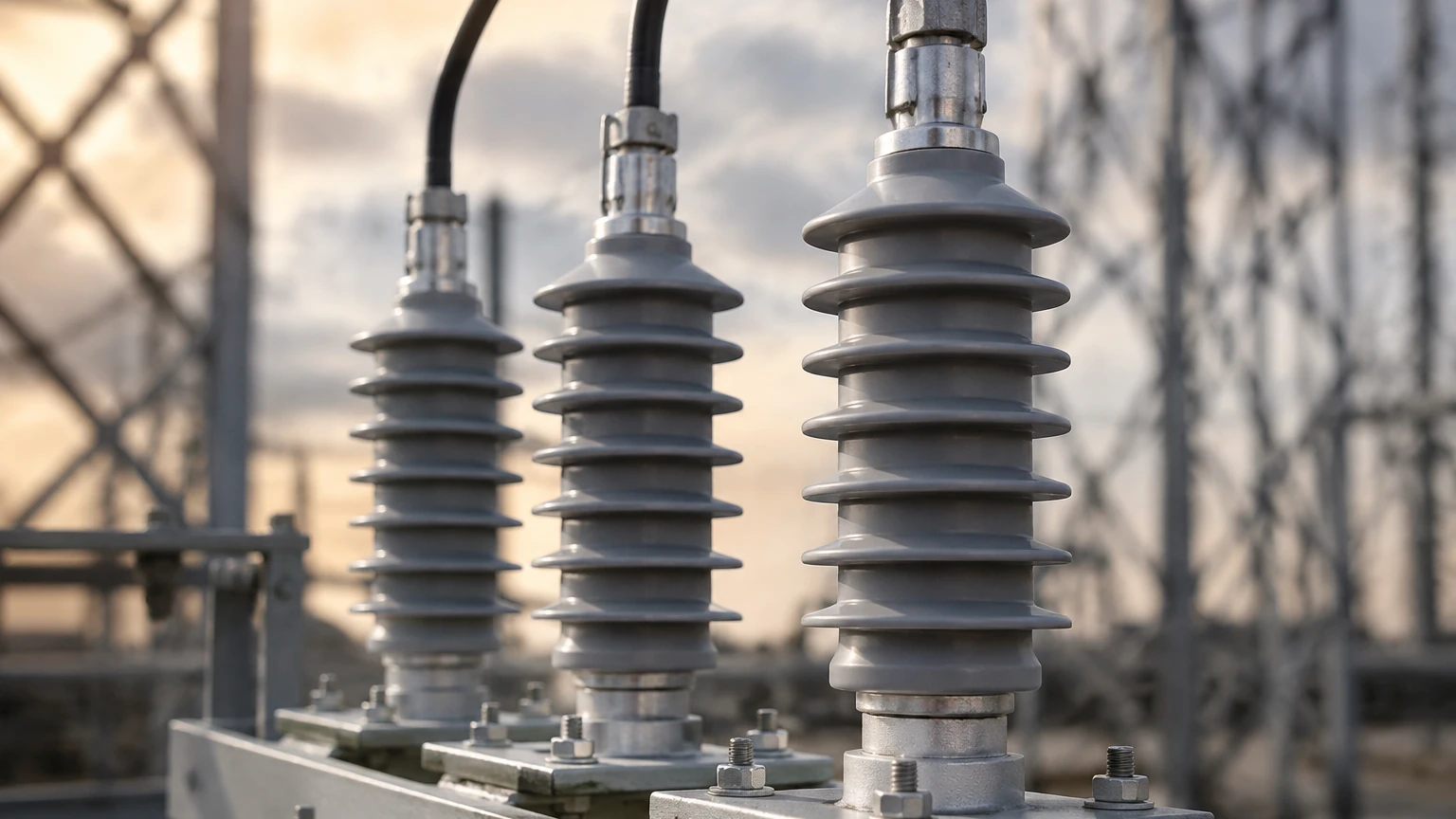
In industrial automation, the reliability of level measurement systems is often compromised not by the mechanical failure of the sensors themselves, but by electrical disturbances. For facilities utilizing radar level meters, ultrasonic sensors, and hydrostatic transmitters, the surge voltage arrester serves as a critical line of defense. These devices are designed to protect sensitive electronic components from transient overvoltages caused by lightning strikes, industrial switching operations, and electrostatic discharges.
In environments such as water treatment plants, chemical processing facilities, and oil storage terminals, level instruments are frequently installed in exposed outdoor locations or atop large metal structures. These conditions significantly increase the risk of surge-related damage. Understanding the selection and application of surge voltage arresters is essential for maintaining system uptime and protecting the investment in high-precision instrumentation found on the Main Page of industrial equipment catalogs.
Understanding Surge Voltage Arrester Principles
A surge voltage arrester, also known as a Surge Protective Device (SPD), operates on the principle of voltage-dependent resistance. Under normal operating conditions, the arrester maintains high impedance, effectively acting as an open circuit that does not interfere with the power or signal flow to the level meter.
When a transient overvoltage occurs—exceeding the device’s threshold—the internal components of the arrester rapidly transition to a low-impedance state. This creates a path of least resistance, diverting the excess surge current safely to the ground and clamping the voltage to a level that the connected equipment can withstand. Once the surge dissipates, the arrester automatically resets to its high-impedance state.
Core Technologies
1. Metal Oxide Varistors (MOV): These are the most common components in surge protection. They offer fast response times and can handle significant energy loads. However, they degrade slightly with each surge event.
2. Gas Discharge Tubes (GDT): These consist of two electrodes in a ceramic tube filled with noble gas. They can handle very high currents but have a slower response time compared to MOVs. They are often used in combination with other technologies.
3. Transient Voltage Suppression (TVS) Diodes: These provide the fastest response times and are ideal for protecting sensitive data lines (such as RS485 or 4-20mA signals), though they have lower energy-handling capacities than GDTs.
Types of Surge Protection for Level Measurement Systems
Industrial level measurement setups require a multi-layered protection strategy. A single arrester at the main power panel is rarely sufficient to protect a sensor located 50 meters away on a tank top.
Power Supply Protection
This involves protecting the AC or DC power lines feeding the transmitters and control systems. In many industrial sites, switching large inductive loads (like heavy-duty pumps or motors) can induce significant surges on the local power grid. Type 1 and Type 2 arresters are typically used at the distribution board, while Type 3 arresters are placed closer to the end device.
Signal and Data Line Protection
Level meters often communicate via 4-20mA loops, HART protocols, or digital buses like Modbus (RS485). These lines are highly susceptible to electromagnetic interference (EMI) and induced surges from nearby lightning strikes. Signal-side surge voltage arresters must have low internal capacitance to ensure they do not distort the high-frequency digital signals used in modern radar and ultrasonic level measurement.
Coaxial and RF Protection
For remote level monitoring systems that utilize wireless transmission or external antennas, specialized coaxial surge arresters are required to prevent atmospheric electricity from entering the radio equipment through the antenna cable.
Key Technical Specifications for Selection
When selecting a surge voltage arrester for an industrial level measurement application, engineers must evaluate several critical parameters to ensure compatibility and effectiveness.
| Parameter | Description | Importance |
| :— | :— | :— |
| Maximum Continuous Operating Voltage ($U_c$) | The maximum voltage that can be continuously applied to the arrester. | Must be higher than the system's nominal voltage to prevent premature activation. |
| Voltage Protection Level ($U_p$) | The maximum voltage the arrester allows to reach the equipment during a surge. | Must be lower than the impulse withstand voltage of the level meter. |
| Nominal Discharge Current ($I_n$) | The peak current (8/20 µs waveform) the device can withstand repeatedly. | Defines the durability and service life of the arrester. |
| Response Time ($t_A$) | The time taken for the arrester to react to a surge. | Critical for protecting sensitive electronics; typically <1ns for diodes and <25ns for MOVs. |
| Bandwidth/Insertion Loss | The impact of the arrester on the signal quality. | Essential for HART and RS485 lines to prevent data errors. |
Installation Best Practices for Industrial Applications
The effectiveness of a surge voltage arrester is heavily dependent on its installation. A poorly installed arrester may fail to protect the equipment even if the device itself is high-quality.
1. The 50cm Rule (Lead Length)
Lead lengths should be kept as short and straight as possible. Every centimeter of wire adds inductance, which increases the voltage drop during a high-frequency surge. It is a standard engineering recommendation that the total lead length (from the line to the arrester and from the arrester to the ground bus) should not exceed 500mm (0.5 meters).
2. Proper Grounding and Bonding
Surge protection is only as good as the grounding system it connects to. The grounding impedance should ideally be less than 10 ohms for industrial sites. Furthermore, all equipment should be connected to a common equipotential bonding system to prevent dangerous potential differences between different parts of the installation during a strike.
3. Physical Placement
For maximum protection, arresters should be installed at both ends of a long cable run—one at the sensor (the field side) and one at the PLC/Control Room (the cabinet side). This protects the sensor from surges induced in the cable and protects the control system from surges originating at the tank.
4. Separation of Wiring
"Clean" wires (those protected by the arrester) should never be run in the same conduit or bundle as "dirty" wires (unprotected lines coming from the field). Surges can easily jump across adjacent wires via inductive coupling, bypassing the protection entirely.
Limitations and Maintenance of Surge Protectors
While highly effective, surge voltage arresters are not "install and forget" devices. They have specific limitations that must be managed through regular maintenance programs.
* Component Degradation: MOVs have a finite life. Each time they absorb a surge, they degrade slightly. Over time, the leakage current increases, eventually leading to device failure. Many modern arresters include a visual status indicator (green for OK, red for Replace).
* Direct Lightning Strikes: No standard surge voltage arrester can guarantee 100% protection against a direct lightning strike to the sensor itself. The goal of the SPD is to manage the induced overvoltages and secondary effects of lightning.
* Environmental Sealing: In chemical or water treatment environments, the arrester housing must match the required IP rating (e.g., IP66 or IP67) or be housed in a suitable junction box to prevent corrosion of the terminals.
Maintenance should include a periodic visual inspection of the status indicators and annual testing of the grounding system's integrity. If a major lightning event occurs in the vicinity, all arresters should be checked immediately.
Frequently Asked Questions (FAQ)
Q: Does a surge voltage arrester affect the accuracy of my 4-20mA level sensor?
A: A correctly selected signal-line arrester has negligible internal resistance (typically a few ohms) and will not affect the accuracy of a standard 4-20mA loop. However, for high-speed digital communications, the capacitance of the arrester must be considered.
Q: If my level meter is grounded to the metal tank, do I still need an arrester?
A: Yes. Grounding the meter housing protects against electric shock and some EMI, but it does not protect the internal electronics from surges traveling through the power or signal wires. An arrester is required to clamp the voltage between the wires and the ground.
Q: Can I use one arrester for multiple sensors?
A: Generally, no. Each signal pair or power feed requires its own dedicated protection. Attempting to parallel multiple signals into one arrester can lead to cross-talk and signal interference.
Q: How do I know if an arrester has failed?
A: Most industrial-grade arresters feature a mechanical indicator or a remote signaling contact. If the indicator turns red, the internal thermal disconnect has triggered, and the module must be replaced to restore protection.
Conclusion
Integrating surge voltage arresters into your level measurement infrastructure is a vital step in ensuring long-term operational stability. By diverting transient energies before they reach sensitive radar or ultrasonic components, these devices prevent costly hardware replacements and unplanned process shutdowns. When designing a system, always prioritize short lead lengths, robust grounding, and the selection of arresters that match the specific electrical characteristics of your instrumentation. For those seeking reliable level measurement hardware and integrated protection solutions, reviewing technical options on the Main Page of professional manufacturers is the best starting point for engineering a resilient system.