Wastewater Treatment Automation
Wastewater Treatment Automation
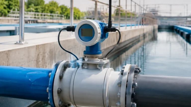
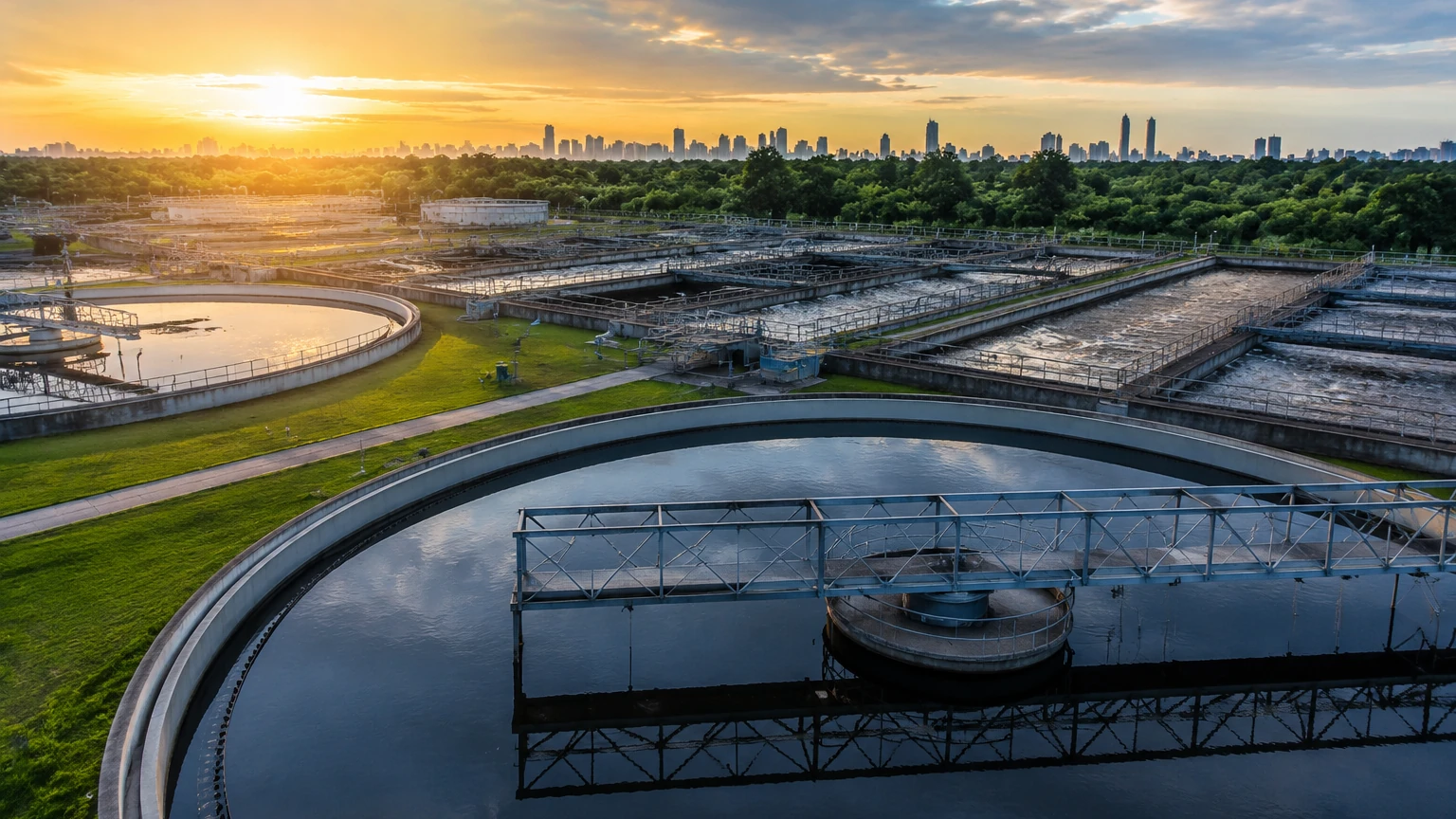
In the modern industrial landscape, wastewater treatment automation has transitioned from a luxury to a technical necessity. As regulatory requirements for effluent quality become more stringent and the costs of energy and chemicals rise, plant operators are increasingly relying on automated systems to optimize performance. At the heart of any automated wastewater process is the ability to accurately measure and monitor fluid levels across various stages of treatment. Reliable data from sensors allows Programmable Logic Controllers (PLCs) and Supervisory Control and Data Acquisition (SCADA) systems to manage pumps, valves, and chemical dosing with precision.
Effective automation reduces human error, prevents overflows, and ensures that biological and chemical processes occur under optimal conditions. This guide examines the foundational technologies of level measurement that drive wastewater treatment automation, offering engineering insights into selection, installation, and system integration.
Core Measurement Principles in Wastewater Automation
Before selecting hardware for an automated system, it is essential to understand the physics behind the primary measurement technologies. In wastewater environments, the presence of foam, turbulence, corrosive chemicals, and suspended solids necessitates a nuanced approach to sensor selection.
Radar Level Measurement (Non-Contact)
Radar level meters operate on the principle of Time Domain Reflectometry (TDR) or Frequency Modulated Continuous Wave (FMCW). The instrument emits high-frequency electromagnetic pulses (typically in the 26GHz or 80GHz range) toward the liquid surface. These pulses are reflected back to the sensor. By measuring the time of flight or the frequency shift, the device calculates the distance to the liquid surface.
* Advantages: Radar is unaffected by air temperature, pressure, or the presence of vapors. High-frequency 80GHz radar offers a narrow beam angle, which is ideal for avoiding internal tank obstructions like agitators or ladders.
* Application: Highly effective for aeration tanks with surface foam or chemical storage tanks containing corrosive acids.
Ultrasonic Level Measurement (Non-Contact)
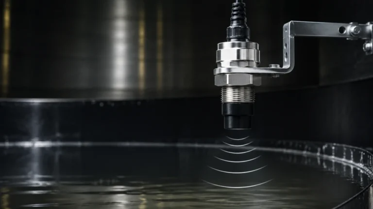
Ultrasonic sensors emit high-frequency sound waves that bounce off the liquid surface. The distance is calculated based on the time it takes for the echo to return. Because the speed of sound is influenced by air temperature, these sensors typically include integrated temperature compensation.
* Advantages: Cost-effective and easy to install for simple applications.
* Limitations: Ultrasonic waves can be absorbed by heavy foam or distorted by significant steam and temperature fluctuations. They require a clear "line of sight" and are sensitive to wind in outdoor applications.
Hydrostatic Pressure Measurement (Contact)
This method relies on the principle that the pressure at the bottom of a liquid column is proportional to the height of the liquid and its density ($P = \rho gh$). A submersible pressure transmitter or a flange-mounted sensor measures this head pressure.
* Advantages: Excellent for deep wells, lift stations, and areas where surface foam makes non-contact measurement difficult.
* Limitations: The sensor is in constant contact with the medium, making it susceptible to clogging or coating if the wastewater has high solids content. It also requires atmospheric pressure compensation via a vented cable.
Integrating Sensors into Wastewater Treatment Automation
For a sensor to contribute to wastewater treatment automation, it must communicate effectively with the broader control architecture. Modern industrial instruments typically utilize the following interfaces:
1. 4-20mA Analog Signals: The industry standard for transmitting level data over long distances with high noise immunity.
2. HART Protocol: Allows digital information to be superimposed on the 4-20mA signal, providing diagnostic data and remote configuration capabilities.
3. Modbus RTU/RS485: A digital communication protocol that allows multiple sensors to be daisy-chained, reducing wiring costs in large-scale facilities.
When these sensors are integrated into a SCADA system, the automation software can execute complex logic. For example, in a lift station, the system can rotate the lead pump to ensure even wear, or trigger emergency alarms if levels rise too rapidly during a storm event. For more detailed technical specifications on sensors compatible with these protocols, engineers can consult the Main Page of professional instrumentation providers.
Engineering Selection Criteria and Application Matrix
Selecting the right instrument requires balancing accuracy requirements, environmental conditions, and maintenance budgets. The following table provides a comparative overview of how different technologies perform in typical wastewater scenarios.
| Application Area | Preferred Technology | Secondary Option | Key Consideration |
| :— | :— | :— | :— |
| Inlet Screening | Ultrasonic | Radar | Monitor head loss across screens. |
| Grit Chambers | Radar | Hydrostatic | Turbulence and solids are common. |
| Aeration Tanks | 80GHz Radar | Ultrasonic | Foam can interfere with ultrasonic signals. |
| Sludge Digesters | Radar | Hydrostatic | Methane gas and high temperatures. |
| Chemical Dosing | Radar | Magnetic Gauge | Resistance to corrosive vapors is critical. |
| Effluent Channels | Ultrasonic | Radar | Open channel flow measurement (Parshall flumes). |
Key Evaluation Criteria
* Accuracy: Does the process require millimeter precision (e.g., chemical dosing) or general level monitoring (e.g., storm tanks)?
* Medium Characteristics: Is the liquid corrosive, prone to foaming, or high in suspended solids?
* Environmental Factors: Will the sensor be exposed to direct sunlight, heavy rain, or explosive gases (requiring ATEX/Ex certification)?
Installation Best Practices and Technical Limitations
Even the most advanced sensor will fail to provide accurate data if installed incorrectly. In the context of wastewater treatment automation, installation errors are a primary cause of system downtime.
1. The "Dead Zone" or Blocking Distance
Every non-contact sensor (Radar and Ultrasonic) has a near-field region where it cannot accurately measure. If the liquid level rises into this zone, the sensor may report an incorrect value or a "loss of echo" error. Always mount the sensor high enough to ensure the maximum liquid level never enters the dead zone.
2. Avoiding Obstructions
Internal structures such as pipes, ladders, and agitators can create false echoes. While modern software can "map out" these fixed obstructions, it is better to install the sensor in a location with a clear path to the liquid surface. For radar, a narrow beam angle (e.g., 3° to 6°) significantly reduces the risk of interference from tank walls.
3. Turbulence and Foam
In aeration tanks or rapid-mix basins, the surface is often turbulent. Using a stilling well (a pipe that surrounds the sensor) can provide a calm surface for measurement. However, in wastewater, stilling wells must be cleaned regularly to prevent the buildup of fats, oils, and grease (FOG).
4. Atmospheric Venting
For hydrostatic transmitters, the reference side of the pressure diaphragm must be vented to the atmosphere. If the vent tube in the cable is kinked or blocked by moisture, the level reading will drift as barometric pressure changes.
Common Risks in Automated Systems
While automation increases efficiency, it introduces specific risks that must be managed:
* Signal Drift: Over time, sensors may require recalibration. In an automated system, a drift of even 5% can lead to significant chemical over-dosing or inefficient pump operation.
* Sensor Coating: In sludge applications, biological growth or grease can coat the face of a sensor. Non-contact radar is generally more resilient to this than ultrasonic or hydrostatic options.
* Lightning and Surges: Since many wastewater sensors are located outdoors in elevated positions, they are vulnerable to lightning strikes. Proper grounding and the use of surge protection devices (SPDs) are essential for protecting the automation hardware.
Frequently Asked Questions (FAQ)
Q: How often should level sensors in a wastewater plant be calibrated?
A: For critical process control, a bi-annual check is recommended. For general monitoring, an annual calibration is usually sufficient. Sensors with internal diagnostics (HART) can often alert operators when they require attention.
Q: Can I use ultrasonic sensors in a sludge digester?
A: It is generally not recommended. Sludge digesters often contain methane and other gases that change the speed of sound, leading to significant errors. Furthermore, the high temperatures and potential for foam make radar a much more reliable choice.
Q: What is the benefit of 80GHz radar over 26GHz radar?
A: The higher frequency (80GHz) allows for a much smaller antenna and a narrower beam. This makes it easier to install in small openings and ensures the signal does not hit the sides of the tank or internal obstructions.
Q: How do I handle level measurement in an open channel?
A: Automation systems typically use an ultrasonic or radar sensor mounted over a flume or weir. The PLC uses a programmed formula (like the Manning equation) to convert the measured level into a flow rate (liters per second or cubic meters per hour).
Conclusion and Next Steps
Implementing wastewater treatment automation requires a holistic understanding of both the mechanical process and the electronic instrumentation. By selecting the appropriate measurement principle—whether it be the robustness of radar, the simplicity of ultrasonic, or the depth-capability of hydrostatic sensors—engineers can build a resilient system that stands up to the harsh conditions of a treatment plant.
Before proceeding with a project, technical teams should confirm the chemical compatibility of sensor materials (such as PVDF or Stainless Steel), verify the required communication protocols for the existing PLC/SCADA architecture, and assess the physical constraints of the installation site. For further assistance in selecting the right instrumentation for your automation needs, you can Review product options and application support to ensure your facility operates at peak efficiency.