Capacitance Level Sensors
Capacitance Level Sensors
In the landscape of industrial process control, the ability to accurately monitor the level of liquids, granulates, and slurries is fundamental to operational efficiency and safety. Capacitance level sensors represent one of the most versatile and established technologies for both point-level detection and continuous level measurement. As a professional manufacturer, Welk provides these instruments to diverse sectors including water treatment, chemical processing, and oil and gas, where robust performance in challenging environments is a prerequisite.
This guide examines the underlying physics of capacitance-based measurement, explores selection criteria for different industrial media, and outlines the technical considerations necessary for successful installation and maintenance.
The Physics of Capacitance Level Measurement
To effectively implement capacitance level sensors, an understanding of the basic electrical principles is required. A capacitor is an electronic component that stores energy in an electrical field between two conductive plates. The ability of this system to store a charge is defined as capacitance (C), measured in Farads (F), though industrial sensors typically operate in the picofarad (pF) range.
The standard formula for capacitance in a parallel-plate capacitor is:
C = ε(A/d)
Where:
- C is the capacitance.
- ε (Epsilon) is the permittivity of the dielectric material between the plates (ε = ε₀ * εᵣ, where ε₀ is the permittivity of free space and εᵣ is the relative dielectric constant).
- A is the surface area of the plates.
- d is the distance between the plates.
How the Sensor Applies This Principle
In an industrial level sensing application, the sensor probe acts as one plate of the capacitor, while the vessel wall (if metallic and grounded) acts as the second plate. If the vessel is non-conductive (e.g., plastic or fiberglass), a second reference probe or a ground strap must be installed to complete the circuit. The material being measured—whether it is water, oil, or a solid—acts as the dielectric medium between these two "plates."
As the level of the material rises, it displaces the air or vapor space (which has a dielectric constant of approximately 1.0). Since most process materials have a higher dielectric constant than air, the total capacitance of the system increases proportionally with the level. The electronics in the sensor head convert this change in capacitance into a standardized output signal, such as a 4-20 mA analog signal for continuous measurement or a relay switch for point-level detection.
The Importance of the Dielectric Constant (εᵣ)
The dielectric constant of the medium is the most critical factor in sensor performance. Materials with high dielectric constants are easier to measure because they produce a more significant change in capacitance for a given change in level.
* Conductive Liquids: Water (εᵣ ≈ 80) and aqueous solutions are highly conductive. In these cases, the probe must be insulated (usually with PTFE or PFA) to prevent a short circuit. The measurement effectively occurs between the probe conductor and the surface of the liquid.
* Non-Conductive Liquids: Oils (εᵣ ≈ 2.0 to 4.0) and solvents have low dielectric constants. These require highly sensitive electronics to detect the subtle changes in capacitance.
* Solids and Powders: Materials like sand, plastic pellets, or grain typically have dielectric constants between 1.5 and 5.0. Measurement accuracy depends on the bulk density and moisture content of the material remaining consistent.
System Components and Configurations
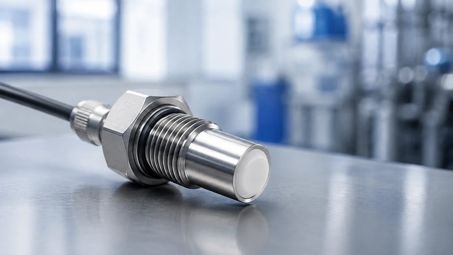
A typical capacitance level sensor system consists of three primary components: the probe (electrode), the insulation, and the transmitter electronics.
1. The Probe: Probes are available as rigid rods for shorter distances (typically up to 3 or 4 meters) or flexible cables for deep tanks and silos (up to 30 meters or more). The choice of material—usually 316 stainless steel—depends on the chemical compatibility of the process media.
2. Insulation: For conductive media or to prevent corrosion, probes are coated with dielectric materials such as PTFE (Polytetrafluoroethylene), PFA (Perfluoroalkoxy), or FEP. The thickness and integrity of this coating are vital for the sensor's calibration and longevity.
3. Transmitter Electronics: The electronics housing, often rated IP65 or higher, contains the circuitry that excites the probe with a high-frequency radio frequency (RF) signal. It processes the return signal and provides the user interface for calibration (setting the 0% and 100% points).
Continuous vs. Point Level Detection
Capacitance technology is adaptable to two primary modes of operation:
Point Level Switches
These sensors are used to detect the presence or absence of material at a specific height. They are commonly used for high-level alarm (overfill protection) or low-level alarm (pump dry-run protection). They are favored for their lack of moving parts, making them more reliable than mechanical float switches in viscous or corrosive liquids.
Continuous Level Transmitters
These provide a constant readout of the level across the entire span of the probe. They are ideal for process monitoring and inventory management. Because the measurement is integrated along the length of the probe, capacitance sensors are particularly effective in agitated tanks where the surface may be turbulent, a condition that can sometimes challenge ultrasonic or radar sensors.
Practical Selection and Application Table
Choosing the correct configuration requires matching the sensor hardware to the physical and chemical properties of the media. The following table provides a general framework for selection:
| Media Type | Conductivity | Recommended Probe Type | Key Consideration |
| :— | :— | :— | :— |
| Water/Aqueous Solutions | High | Fully Insulated (PTFE/PFA) | High εᵣ allows for very stable measurement. |
| Oils/Hydrocarbons | Low | Bare Metal or Thinly Insulated | Requires sensitive electronics; sensitive to moisture ingress. |
| Corrosive Acids | High | Fully Insulated (Specialty Plastics) | Chemical compatibility of the wetted parts is paramount. |
| Dry Powders/Grains | Low | Rigid Rod or Cable (Non-insulated) | Bulk density must be stable; avoid high-impact loading on the probe. |
| Slurries/Viscous Liquids | Variable | Insulated with Active Shield | Coating buildup can cause false readings; requires "Admittance" technology. |
| High Temp/Pressure | Variable | Ceramic or High-Temp Insulators | Ensure the seal at the process connection can withstand the pressure. |
Installation and Engineering Best Practices
Proper installation is essential to ensure the accuracy of capacitance level sensors. Engineers should adhere to the following guidelines:
Grounding and Reference
For the capacitor to function, a return path for the electrical field is required. In metallic tanks, the tank wall serves this purpose, provided the sensor is electrically bonded to the tank. In non-metallic tanks (plastic, concrete, or lined vessels), a reference electrode must be used. This can be a second rod installed parallel to the main probe or a concentric ground tube (coaxial probe) that surrounds the measuring electrode.
Mounting Location
* Avoid the Inflow: Do not mount the probe directly in the path of the falling material during tank filling. This can cause physical damage to the probe and result in erratic readings due to the turbulence.
* Proximity to Walls: Maintain a consistent distance from the tank walls and internal structures (like ladders or agitators). For a standard rod probe, a minimum distance of 100 mm to 300 mm from the wall is usually recommended to prevent interference.
* Dead Zones: Be aware of the "inactive length" at the top of the probe near the mounting thread. Measurement cannot occur in this region, so the probe length must be specified to account for the desired measurement range.
0
Vessel Geometry
In horizontal cylindrical tanks, the relationship between level and volume is non-linear. While the capacitance sensor measures the linear level, the transmitter or the control system (PLC/DCS) must be programmed with a strapping table or volume formula to provide accurate inventory data.
Addressing Limitations: Material Buildup and Dielectric Shifts
While capacitance level sensors are highly versatile, they face two primary challenges: material buildup and changes in the dielectric constant.
Coating and Buildup
In applications involving sticky or viscous media, material can adhere to the probe. If this coating is conductive, the sensor may continue to "see" the material even after the level has dropped, leading to a false high reading. To combat this, Welk and other advanced manufacturers utilize RF Admittance technology. This is an evolution of capacitance measurement that uses a "driven shield" or "guard" section on the probe. By applying a voltage to the shield that is identical in frequency and phase to the measuring electrode, the sensor can ignore the current flow through the buildup and measure only the change in the bulk level.
Dielectric Variability
Capacitance measurement assumes the dielectric constant of the material remains stable. If the composition of the liquid changes—for example, if the moisture content in a grain silo fluctuates significantly or if different chemicals are mixed in a batch process—the sensor may require recalibration. In processes where the dielectric constant varies frequently, technologies like radar or hydrostatic pressure might be more appropriate, or a compensating reference probe may be installed.
Frequently Asked Questions (FAQ)
Q: Can capacitance sensors be used in vacuum or high-pressure tanks?
A: Yes. Since capacitance measurement does not rely on air pressure or sound waves, it functions perfectly well in a vacuum. High-pressure versions are available, provided the process connection and probe seals are rated for the specific pressure and temperature of the vessel.
Q: How do I calibrate a capacitance level sensor?
A: Most modern sensors feature a two-point calibration. You typically calibrate the "Zero" point when the tank is empty (or at the lowest desired level) and the "Span" point when the tank is full (or at the highest desired level). Some advanced units allow for "dry calibration" if the dielectric constant of the material is known.
Q: What happens if the probe touches the tank wall?
A: If a bare probe touches a metallic tank wall, it will short circuit, resulting in an error or a maximum-scale reading. If the probe is insulated, contact with the wall will significantly alter the capacitance and cause inaccurate readings. Proper tensioning of cable probes and correct placement of rigid probes are necessary to prevent this.
Q: Are capacitance sensors affected by foam?
A: It depends on the foam's density and conductivity. Light, airy foam often has a dielectric constant close to 1.0 and may be ignored by the sensor. However, dense, wet foam may be detected as a liquid level. Testing is usually required for specific foaming applications.
Conclusion
Capacitance level sensors remain a cornerstone of industrial instrumentation due to their reliability, lack of moving parts, and adaptability to extreme temperatures and pressures. By understanding the dielectric properties of the media and ensuring rigorous installation standards, engineers can achieve highly accurate level monitoring in even the most demanding environments. For those seeking to explore specific hardware configurations or obtain technical support for a custom application, please visit our Main Page to review product options and application support. Welk continues to provide advanced measurement solutions tailored to the evolving needs of global industrial automation.