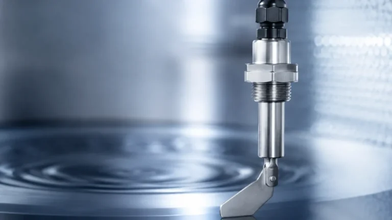
Mass Flow Meter Air
Mass Flow Meter Air
In industrial process control, the measurement of air flow is a fundamental requirement for optimizing combustion, managing compressed air systems, and ensuring the efficiency of HVAC and pneumatic conveying processes. While volumetric flow measurement was historically the standard, the shift toward a mass flow meter air approach has become the benchmark for precision. Because air is a compressible fluid, its volume changes significantly with variations in temperature and pressure. Measuring the mass—the actual number of molecules passing a point—provides a consistent data point regardless of environmental fluctuations.
For engineers and facility managers, selecting the correct instrumentation requires an understanding of the underlying physics, the specific demands of the application, and the integration of these sensors into broader automation systems. This guide explores the technical principles of air mass flow measurement, selection criteria, and best practices for industrial implementation.
Measurement Principles for Air Mass Flow
To accurately determine the mass flow of air, several technologies are employed, each with distinct advantages based on the flow profile, pipe size, and required accuracy.
Thermal Dispersion Technology
Thermal dispersion is the most widely used principle for a mass flow meter air application. It operates on the premise that a moving gas will carry heat away from a heated surface. The instrument typically features two RTD (Resistance Temperature Detector) sensors: one that measures the actual process temperature (the reference sensor) and another that is heated to a specific temperature above the reference.
As air flows over the heated sensor, the molecules carry away heat energy. The instrument electronics measure the amount of power required to maintain the constant temperature differential. Since the cooling effect is directly related to the number of molecules (the mass) passing the sensor, the meter provides a direct mass flow reading without needing additional pressure or temperature compensation. This technology is particularly valued for its high sensitivity at low flow rates and its lack of moving parts.
Differential Pressure (DP) with Compensation
Differential pressure remains a staple in heavy industry. By placing a primary element, such as an orifice plate or a Pitot tube, into the flow stream, a pressure drop is created. According to Bernoulli’s principle, the square root of this pressure drop is proportional to the flow velocity.
However, to convert this to mass flow for air, the system must also measure the static pressure and the process temperature. An integrated multivariable transmitter then calculates the mass flow using the ideal gas law or real gas equations. While more complex due to the need for multiple sensors, DP flow meters are robust in high-temperature and high-pressure environments.
Coriolis Mass Flow
Coriolis meters provide the highest accuracy by measuring the inertia of the air as it flows through vibrating tubes. The phase shift in the vibration is directly proportional to the mass flow rate. While exceptionally accurate, Coriolis meters are often more expensive and can experience a significant pressure drop when used with low-density gases like air at low pressures. They are typically reserved for high-value applications or high-pressure air distribution where extreme precision is mandatory.
Why Mass Flow Matters: The Compressibility Factor
In industrial settings, air is rarely at a constant state. Consider a compressed air line: the pressure might fluctuate between 6 bar and 8 bar (0.6 to 0.8 MPa), and the temperature might rise as the compressors run throughout the shift.
A volumetric flow meter (like a standard turbine or vortex meter without compensation) would report different volumes for the same amount of actual air mass as these conditions change. This leads to inaccuracies in leak detection, cost allocation, and process stoichiometry. A dedicated mass flow meter air solution eliminates these variables by reporting in Standard Liters per Minute (SLPM) or Normal Cubic Meters per Hour (Nm³/h), which are units of mass disguised as volume at a defined reference state.
For comprehensive process monitoring, integrating these flow measurements with reliable tank and vessel data is essential. Engineers often pair flow data with advanced level measurement solutions from manufacturers like Welk to ensure total mass balance across a facility.
Key Evaluation Criteria for Selection
When specifying a mass flow meter for air, several technical parameters must be evaluated to ensure long-term reliability and performance.
Turndown Ratio (Rangeability)
Air flow in industrial plants can vary wildly. A compressed air system might have high demand during the day and very low demand (only leaks) at night. The turndown ratio represents the range between the maximum and minimum flow the meter can accurately measure. Thermal mass meters often offer turndown ratios of 100:1 or higher, making them ideal for detecting both peak usage and small leaks.
Pressure Drop
Energy efficiency is a primary concern in air systems. Any obstruction in the pipe, such as an orifice plate or a bent Coriolis tube, creates a pressure drop. This forces compressors to work harder, increasing energy costs. Thermal dispersion meters, particularly insertion styles, offer negligible pressure drop, contributing to overall system efficiency.
Response Time
In applications like burner control or rapid pneumatic cycling, the speed at which the meter reacts to changes in flow is critical. Thermal sensors with small mass and advanced digital signal processing provide the fast response times required for dynamic control loops.
Accuracy and Repeatability
Accuracy is typically expressed as a percentage of the reading or a percentage of the full scale. For air mass flow, an accuracy of ±1% of the reading is standard for high-quality thermal meters. Repeatability is equally important for process consistency, ensuring the meter provides the same output for the same flow conditions day after day.
Selection Table: Comparing Air Flow Technologies
| Feature | Thermal Dispersion | Differential Pressure | Coriolis |
| :— | :— | :— | :— |
| Direct Mass Measurement | Yes | No (Requires P & T) | Yes |
| Accuracy | ±1% to ±5% | ±1% to ±3% | ±0.5% or better |
| Pressure Drop | Very Low | High | Moderate to High |
| Turndown Ratio | 100:1 | 4:1 | 20:1 |
| Moving Parts | None | None | None (Vibrating) |
| Typical Application | Compressed air, HVAC | Large ducts, Steam/Air | High-pressure gas |

Installation Considerations
The performance of a mass flow meter air is heavily dependent on proper installation. Even the most accurate sensor will provide erroneous data if the flow profile is disturbed.
1. Straight Pipe Runs: To ensure a fully developed laminar flow profile, meters require a minimum length of straight pipe both upstream and downstream of the sensor. A common rule of thumb is 10 to 20 diameters upstream and 5 diameters downstream. If elbows, valves, or reducers are present, these requirements increase.
2. Orientation: For thermal mass meters, the orientation of the probe is vital. In horizontal pipes, the probe is often installed at the 2 o'clock or 10 o'clock position to avoid moisture accumulation at the bottom of the pipe or air pockets at the top.
3. Moisture and Contamination: While thermal meters are robust, heavy moisture or oil mist can coat the sensor, leading to measurement errors (as the water carries away more heat than the air). In such cases, water traps or specialized sensor designs with self-cleaning capabilities are necessary.
4. Insertion vs. In-line: For small pipes (typically below 50 mm), in-line meters with built-in flow conditioners are preferred. For larger ducts and pipes, insertion meters provide a cost-effective solution but require precise alignment with the flow direction.
Limitations and Common Risks
While mass flow meters are highly effective, engineers must be aware of potential pitfalls:
* Gas Composition Changes: Thermal mass meters are calibrated for a specific gas mixture (e.g., 79% Nitrogen, 21% Oxygen). If the air composition changes significantly—for example, if it is enriched with Oxygen or contains high levels of CO2—the meter must be recalibrated or the flow computer must be updated with the new gas properties.
* Extreme Velocities: At very high velocities, the cooling effect on a thermal sensor may saturate, leading to a loss of accuracy. Conversely, at extremely low velocities, natural convection can interfere with the measurement.
* Installation Errors: Bypassing the recommended straight-run requirements is the most frequent cause of measurement failure in the field. Using flow conditioners can mitigate this if space is limited.
Integration with Industrial Systems
Modern air mass flow meters are rarely standalone devices. They typically output data via 4-20mA signals, Modbus RTU, or Profibus to a PLC (Programmable Logic Controller) or SCADA system. This integration allows for real-time monitoring of energy intensity—calculating the kilowatts of electricity used per cubic meter of air produced.
In many process industries, flow measurement is the "dynamic" side of the equation, while level measurement is the "static" or inventory side. For instance, in a pneumatic conveying system, monitoring the air mass flow ensures the product is moving at the correct velocity, while level sensors (such as those found on the Main Page of instrumentation specialists) monitor the silos to prevent overfilling or dry-run conditions.
Frequently Asked Questions (FAQ)
Q: Does a thermal mass flow meter need frequent recalibration?
A: Because there are no moving parts to wear out, these meters are very stable. However, an annual calibration check is recommended to ensure that sensor coating or environmental factors haven't caused a drift in accuracy.
Q: Can I use a mass flow meter for air to measure other gases?
A: Yes, but the meter must be programmed for the specific thermal properties (thermal conductivity and specific heat) of that gas. Most modern digital meters allow for field-selection of common gases.
Q: How do I handle wet air in a compressed air system?
A: If the air is saturated with water droplets, it is best to install the flow meter after the air dryer. If that is not possible, use an insertion meter with a protective shroud and install it in a vertical pipe run with upward flow to prevent water from pooling on the sensor.
Q: What is the difference between SCFM and ACFM?
A: ACFM (Actual Cubic Feet per Minute) is a volumetric measurement at the current operating pressure and temperature. SCFM (Standard Cubic Feet per Minute) is a mass flow measurement referenced to a standard set of conditions (usually 14.7 psia and 60°F or 70°F). A mass flow meter provides data directly in SCFM.
By understanding these principles and selecting the appropriate technology for the specific environmental conditions, industrial operators can achieve precise control over their air systems, leading to significant energy savings and improved process reliability.