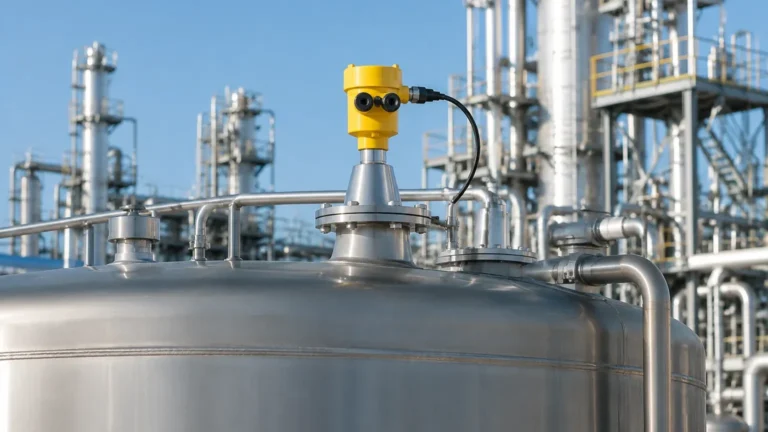
5402 Radar Level Transmitter Manual
5402 Radar Level Transmitter Manual: Engineering Guide and Selection Reference
In the landscape of industrial process automation, the 5402 radar level transmitter represents a critical component for non-contacting level measurement. Designed to handle the complexities of liquid and slurry monitoring, this instrument utilizes high-frequency microwave technology to deliver precision in environments where traditional contact-based sensors often fail. This manual provides a comprehensive engineering overview of the operating principles, installation requirements, and selection criteria for Radar Level Meters, specifically focusing on the 5402 series architecture.
Understanding Radar Level Measurement Principles
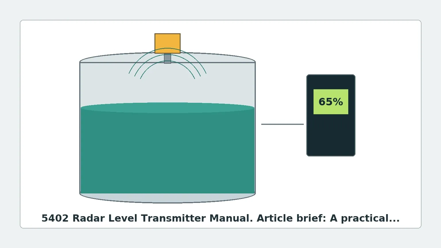
The 5402 radar level transmitter operates on the Frequency Modulated Continuous Wave (FMCW) principle or high-frequency pulsed technology, depending on the specific hardware revision. Unlike ultrasonic sensors that rely on sound waves, radar transmitters emit electromagnetic pulses that travel at the speed of light.
The FMCW Principle
In an FMCW system, the transmitter emits a continuous signal with a constantly changing frequency. When the signal reflects off the surface of the medium and returns to the antenna, it is compared with the signal being transmitted at that exact moment. The frequency difference between the transmitted and received signals is directly proportional to the distance to the product surface. This method provides superior accuracy and signal-to-noise ratios compared to older pulsed radar systems.
Signal Propagation and Dielectric Constants
The reliability of the measurement is heavily dependent on the dielectric constant (εr) of the material being measured. Materials with high dielectric constants, such as water (εr ≈ 80), reflect a strong signal. Conversely, hydrocarbons and oils (εr ≈ 2.0) reflect much less energy. The 5402 is engineered with high-sensitivity electronics to process these weaker signals, but understanding the medium's properties is the first step in any technical manual review.
Technical Specifications and Selection Criteria
Selecting the correct configuration for a 5402 radar level transmitter requires a detailed analysis of the process conditions. The following table outlines the standard engineering specifications typically encountered in the 5402 radar level transmitter manual.
| Feature | Specification | Engineering Note |
| :— | :— | :— |
| Measurement Range | Up to 35 meters (115 ft) | Dependent on antenna type and dielectric constant. |
| Frequency | 24 GHz to 26 GHz (K-band) | Higher frequency allows for smaller antennas and narrower beam angles. |
| Accuracy | ±2 mm to ±5 mm | Varies based on distance and environmental stability. |
| Process Temperature | -40°C to +250°C | Requires high-temperature spacers for extremes. |
| Process Pressure | Vacuum to 40 bar (580 psi) | Flange rating must match vessel requirements. |
| Output Signal | 4-20 mA with HART, Modbus, or FF | Digital integration for remote diagnostics. |
| Beam Angle | 8° to 20° | Narrower beams reduce interference from internal tank structures. |
Antenna Selection
The antenna is the interface between the instrument and the process. The 5402 typically supports several styles:
1. Cone/Horn Antennas: The most versatile option, suitable for most large vessels and high-dielectric liquids.
2. Rod Antennas: Ideal for small nozzles or corrosive environments where PTFE cladding is required.
3. Parabolic Antennas: Used for long-range measurements or materials with very low dielectric constants.
Installation and Mounting Considerations
Proper installation is the single most important factor in ensuring the longevity and accuracy of a radar level transmitter. Engineers must adhere to strict geometric constraints to avoid "false echoes" from tank walls or internal obstructions.
Positioning the Transmitter
* The 1/6th Rule: For cylindrical tanks, the transmitter should ideally be installed at 1/6th of the tank diameter from the outer wall. This avoids the center of the tank where multiple reflections can converge, and stays far enough from the wall to prevent signal attenuation.
* Nozzle Geometry: The nozzle height should be kept as short as possible. If the nozzle is too long, the radar signal may reflect off the bottom edge of the nozzle before entering the tank, creating a "dead zone" or interference at the top of the measurement range.
* Obstruction Clearance: Ensure the signal beam path is clear of ladders, agitators, heating coils, or inflow streams. The beam spreads as it travels; a 10° beam will have a diameter of approximately 1.7 meters at a distance of 10 meters.
Mounting Orientation
The transmitter should be mounted vertically. Even a slight tilt can cause the signal to reflect away from the antenna, resulting in signal loss (Loss of Echo). In tanks with agitated surfaces, a stilling well or bypass chamber may be necessary to provide a calm surface for measurement.
Configuration and Commissioning Procedures
Once installed, the 5402 must be commissioned according to the steps outlined in the 5402 radar level transmitter manual. Most modern units utilize HART communication for configuration via a handheld communicator or PC-based software.
Basic Setup Parameters
1. Tank Height (Reference Point): Define the distance from the sensor flange to the zero-level point (usually the bottom of the tank).
2. Calibration Range: Set the 4mA (0%) and 20mA (100%) points. Note that the 100% point should never be higher than the "Upper Blocking Distance" (Dead Zone) of the sensor.
3. Damping: Adjust the damping value (usually 0 to 60 seconds) to smooth out fluctuations caused by surface turbulence or agitator blades.
Echo Mapping (False Echo Suppression)
One of the most powerful features of the 5402 is the ability to record an "echo curve" of an empty tank. The software identifies static reflections from internal structures (like support beams) and creates a threshold map. The transmitter will then ignore any signals that fall below this threshold, ensuring that only the actual product level is reported.
Application Scope and Environmental Limitations
While Radar Level Meters are highly robust, certain process conditions require specialized engineering considerations.
Foam and Turbulence
Heavy, dense foam can absorb radar signals, leading to a "Loss of Echo" (LOE) condition. If the foam is light and airy, the radar may pass through it and measure the liquid level underneath. For applications with persistent thick foam, a guided wave radar or a mechanical level gauge may be more appropriate.
Dust and Vapor
High-frequency radar (26 GHz) is generally unaffected by heavy dust or vapor. However, extreme steam or high-pressure CO2 can change the dielectric constant of the medium through which the signal travels, potentially causing a small measurement error (usually <1%).
Corrosive Environments
In chemical processing, the 5402 should be specified with wetted parts made of Hastelloy C, Monel, or Tantalum, or equipped with a PTFE/PFA shield to protect the antenna from aggressive vapors.
Maintenance and Troubleshooting
Industrial radar transmitters are designed for low maintenance, as they have no moving parts. However, periodic inspections are recommended.
* Antenna Cleaning: In applications with crystallizing or viscous media, product buildup on the antenna can attenuate the signal. Many 5402 models offer an integrated air purge connection to keep the antenna face clean.
* Diagnostic Alerts: Modern units provide NE107 compliant diagnostics. Common alerts include:
* Low Signal Strength: Often caused by antenna coating or a low-dielectric product.
* Electronics Temperature: Indicates the housing is exceeding its thermal limits.
* Configuration Error: Usually occurs when the programmed tank height is inconsistent with the measured distance.
Buyer Confirmation Checklist
Before finalizing a purchase or specifying a unit for a project, international procurement teams and engineers should confirm the following data points to ensure the equipment matches the site requirements:
1. Process Connection: Confirm flange size (DN or ANSI), rating (PN16, Class 150, etc.), and material.
2. Hazardous Area Certification: Does the site require ATEX, IECEx, or FM approvals? Is an Intrinsically Safe (Ex ia) or Explosion-Proof (Ex d) housing needed?
3. Minimum Dielectric Constant: Confirm the εr of the medium. If it is below 1.5, specialized high-sensitivity hardware or a stilling well is mandatory.
4. Cable Entry: Specify the thread type (M20x1.5 or 1/2" NPT) to match local electrical conduit standards.
5. Integration Protocol: Ensure the output (HART, Profibus, etc.) is compatible with the existing Distributed Control System (DCS) or PLC.
Frequently Asked Questions (FAQ)
Q: Can the 5402 measure solids like powders or grains?
A: While primarily designed for liquids, high-frequency radar can measure solids. However, for solids, the angle of repose must be considered, and a swiveling flange is often required to aim the beam at the material surface effectively.
Q: What is the "Dead Zone"?
A: The dead zone, or upper blocking distance, is the area immediately below the antenna where the transmitter cannot accurately measure. For the 5402, this is typically between 100mm and 300mm depending on the antenna type.
Q: Does the tank material affect the measurement?
A: For non-contacting radar, the tank material (metal vs. plastic) does not affect the measurement of the product level, but it does affect how the signal behaves. Metal tanks act as Faraday cages, containing the signal, while plastic tanks allow the signal to pass through, which may require external shielding or different mounting strategies.
By following the guidelines in this 5402 radar level transmitter manual overview, engineering teams can ensure high reliability and precision in their level monitoring applications, reducing downtime and optimizing process efficiency.