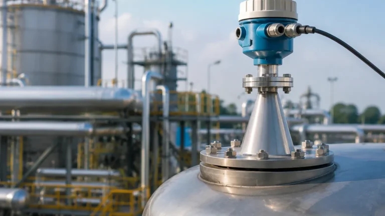
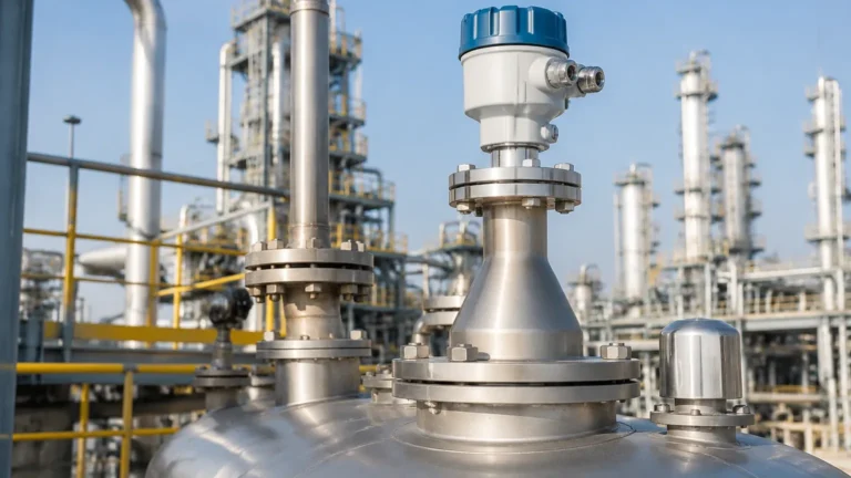
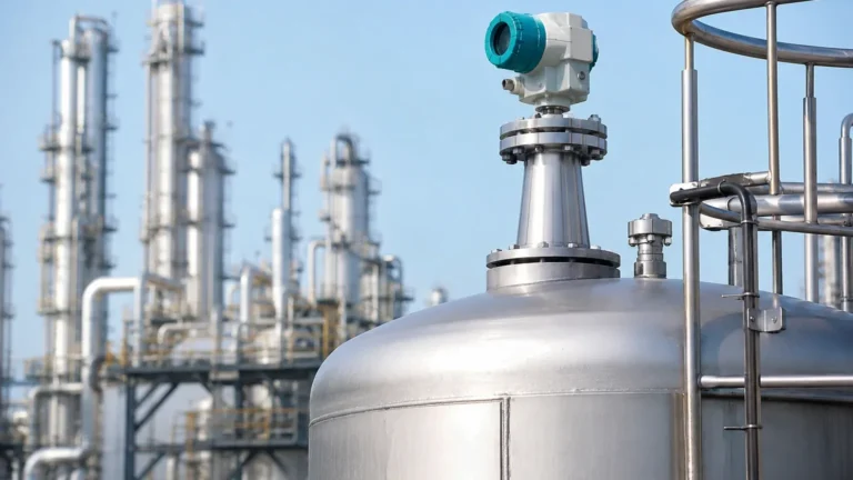
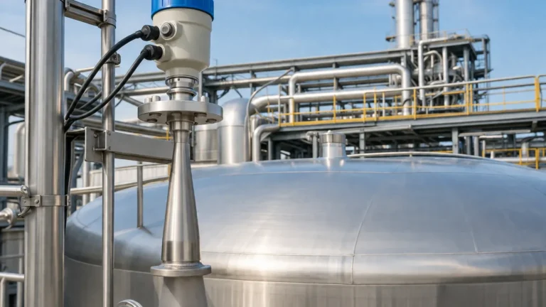
Radar Level Transmitter Gwr
Radar Level Transmitter GWR: A Comprehensive Engineering Guide
In the field of industrial process control, accurate level measurement is essential for operational safety, inventory management, and process efficiency. Among the various technologies available, the radar level transmitter GWR (Guided Wave Radar) has emerged as one of the most versatile and reliable solutions for both liquid and solid applications. Unlike non-contact radar systems that broadcast electromagnetic waves through the air, GWR systems guide the signal along a physical probe, offering distinct advantages in challenging environments.
This guide provides a detailed technical overview of GWR technology, its operating principles, probe selection criteria, and practical installation considerations for engineering professionals.
1. Measurement Principles: Time Domain Reflectometry (TDR)
The fundamental technology behind a radar level transmitter GWR is Time Domain Reflectometry (TDR). This principle is similar to that used in cable testing to locate breaks in underground wires.
How TDR Works in Level Measurement
1. Pulse Emission: The transmitter electronics generate low-power, high-frequency electromagnetic pulses (typically in the gigahertz range).
2. Guided Propagation: These pulses are guided down a probe (the waveguide), which acts as the transmission medium. Because the energy is confined to the probe, signal attenuation is significantly lower than in open-air radar systems.
3. Reflection: When the pulse reaches the surface of the process medium (liquid or solid), a portion of the pulse energy is reflected back toward the transmitter. This reflection occurs due to the change in the dielectric constant (εr) between the upper medium (usually air or vapor) and the process material.
4. Time-of-Flight Calculation: The transmitter's high-speed timing circuit measures the time interval between the pulse emission and the arrival of the reflected echo. Since the speed of light is constant, the distance to the product surface is calculated using the formula:
*Distance = (Speed of Light × Time of Flight) / 2*.
The Role of the Dielectric Constant
The dielectric constant (εr) of the material is the most critical factor in GWR performance. It determines how much energy is reflected.
* High Dielectric Materials: Water (εr ≈ 80) reflects almost the entire signal, providing a very strong echo.
* Low Dielectric Materials: Hydrocarbons, oils, and solvents (εr ≈ 1.4 to 3.0) reflect only a small portion of the signal.
For materials with very low dielectric constants, the remaining signal energy continues down the probe. This characteristic allows GWR transmitters to perform "interface measurement," where they can detect the top of a low-dielectric liquid (like oil) and the surface of a high-dielectric liquid (like water) simultaneously.
2. Comparison: GWR vs. Non-Contact Radar Level Meters
While both technologies utilize microwave pulses, the choice between a radar level transmitter GWR and non-contact Radar Level Meters depends on the specific vessel geometry and process conditions.
| Feature | Guided Wave Radar (GWR) | Non-Contact Radar |
| :— | :— | :— |
| Measurement Path | Physical probe (contacting) | Open air (non-contacting) |
| Signal Strength | High (energy is concentrated) | Lower (signal spreads out) |
| Foam Influence | Minimal; probe penetrates foam | Can be significant; foam absorbs signal |
| Dust/Vapor | Unaffected | Can affect signal at high frequencies |
| Internal Obstacles | Unaffected if probe is clear | Echoes can bounce off agitators/pipes |
| Maintenance | Probe may require cleaning | Minimal (no contact) |
| Max Range | Typically up to 30m – 60m | Can exceed 100m |
3. Probe Configurations and Selection
Selecting the correct probe type is essential for the success of a GWR installation. Probes are generally categorized into three designs: coaxial, twin-rod/cable, and single-rod/cable.
Coaxial Probes
Coaxial probes consist of a central rod inside an outer tube. This design provides the highest signal-to-noise ratio because the electromagnetic field is completely contained within the tube.
* Best for: Low dielectric liquids (εr ≥ 1.4), turbulent surfaces, and tanks with internal obstructions close to the sensor.
* Limitations: Not suitable for viscous liquids or materials that cause buildup, as the narrow space between the rod and tube can clog.
Twin-Rod or Twin-Cable Probes
These utilize two parallel conductors. They offer better signal efficiency than single rods but are less efficient than coaxial designs.
* Best for: General liquid applications and some solids.
* Limitations: Prone to "bridging," where material gets stuck between the two rods, causing false high-level readings.
Single-Rod or Single-Cable Probes
This is the most common configuration for industrial use. The signal travels along a single conductor and uses the tank wall or a reference plate as the ground return.
* Best for: Viscous liquids, slurries, and solids where buildup is a concern. They are the easiest to clean.
* Limitations: Requires a minimum distance from the tank wall and internal obstacles to avoid interference. They are less effective for very low dielectric materials (εr < 2.0).
Selection Summary Table
| Application | Recommended Probe | Reason |
| :— | :— | :— |
| Clean Water/Chemicals | Single Rod (Rigid) | Cost-effective, reliable. |
| Deep Silos (Solids) | Single Cable (Flexible) | Handles tensile loads and long distances. |
| Oil/Hydrocarbon | Coaxial | High sensitivity for low dielectric. |
| Interface (Oil/Water) | Coaxial or Single Rod | Depends on dielectric and viscosity. |
| Aggressive Acids | PFA/PTFE Coated Rod | Corrosion resistance. |
4. Installation Considerations and Constraints
Proper installation of a radar level transmitter GWR ensures long-term accuracy and prevents signal loss. Engineers should adhere to the following guidelines:
Nozzle Geometry
The mounting nozzle should be as short as possible. If the nozzle is too narrow or too long, the radar signal may reflect off the nozzle wall before entering the tank, creating a "dead zone" at the top of the measurement range.
Internal Obstructions
For single-rod probes, a minimum clearance (typically 100mm to 300mm / 4" to 12") must be maintained from the probe to any metal objects, such as agitators, ladders, or the tank wall. If the probe touches a metal object, it will create a false reflection. Coaxial probes are immune to this issue.
The Upper and Lower Dead Zones
Every GWR transmitter has an "Upper Blocking Distance" (Upper Dead Zone) and a "Lower Dead Zone."
* Upper Dead Zone: The area near the mounting flange where the signal is too close to the emission pulse to be accurately distinguished. Measurement is not possible in this region (typically 50mm to 200mm).
* Lower Dead Zone: The area at the very tip of the probe where the signal reflection is influenced by the end of the probe. Accuracy typically degrades in this last 50mm to 100mm.
Grounding and Reference
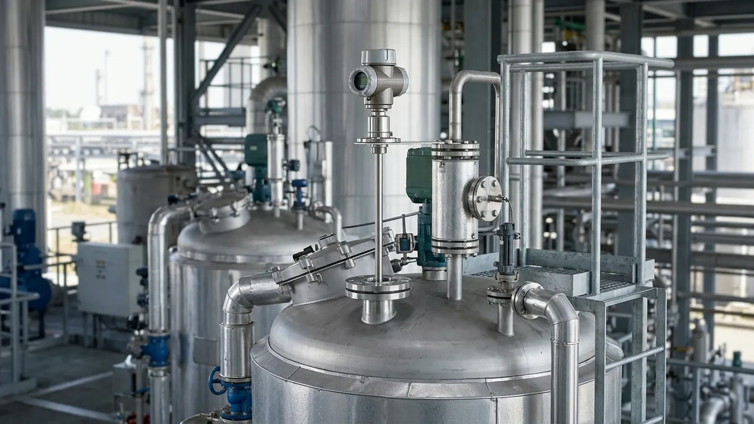
Since single-rod GWR systems rely on the tank wall as a reference, they work best in metal tanks. For plastic or fiberglass tanks, a "bypass pipe" (stilled well) or a large metal mounting flange (launch plate) is required to provide a sufficient ground reference for the signal.
5. Application Risks and Limitations
While robust, a radar level transmitter GWR is not a universal solution. Engineers must account for the following risks:
1. Material Buildup: While single rods handle buildup better than coaxial probes, extreme coating (especially conductive coating like wet coal or metallic slurries) can attenuate the signal or cause "ghost" echoes.
2. Tensile Loads in Solids: In tall grain or mineral silos, the downward pull of the material on a cable probe can be several tons. The transmitter mounting and the tank roof must be engineered to withstand these structural loads.
3. Low Dielectric Limits: If the material has a dielectric constant below 1.4, the reflection may be too weak for the transmitter to detect. In such cases, a bypass pipe or coaxial probe is mandatory.
4. Probe Length Stability: In high-velocity turbulent tanks, long rigid probes can bend or break due to mechanical stress. Flexible cable probes with a bottom weight are often preferred in these scenarios.
6. Frequently Asked Questions (FAQs)
Q: Can GWR measure the level of foam?
A: Generally, GWR signals pass through low-density foam and reflect off the liquid surface beneath. This makes it superior to ultrasonic or non-contact radar in foaming applications. However, very dense, wet foam may produce a reflection of its own.
Q: Is GWR affected by vacuum or high pressure?
A: No. Because the signal propagation does not depend on air density, GWR is ideal for vacuum tanks or high-pressure boilers (up to 400 bar / 5800 psi in specialized models).
Q: How do I handle a probe that is too long?
A: Most rigid rod probes can be cut to length in the field. However, the transmitter electronics must be recalibrated to the new probe length to maintain accuracy. Cable probes are also easily shortened.
Q: Can I use GWR in a bypass chamber?
A: Yes, GWR is frequently used in bypass chambers (magnetic level gauge style). This configuration effectively turns a single rod probe into a coaxial-like system, providing excellent signal stability.
7. Conclusion
The radar level transmitter GWR is a powerful tool for industrial level measurement, offering immunity to dust, vapor, and most foam types. By understanding the dielectric properties of the process medium and selecting the appropriate probe geometry—whether coaxial, rod, or cable—engineers can implement a highly accurate and low-maintenance level solution.
For complex applications involving high temperatures (up to 450°C / 842°F) or extreme pressures, it is recommended to consult with technical specialists to ensure the selected instrument meets the specific safety and material compatibility requirements of the site.
To explore specific hardware configurations and technical specifications for your next project, you may Review product options and application support to find the ideal match for your industrial environment.