Ast 35
Ast 35
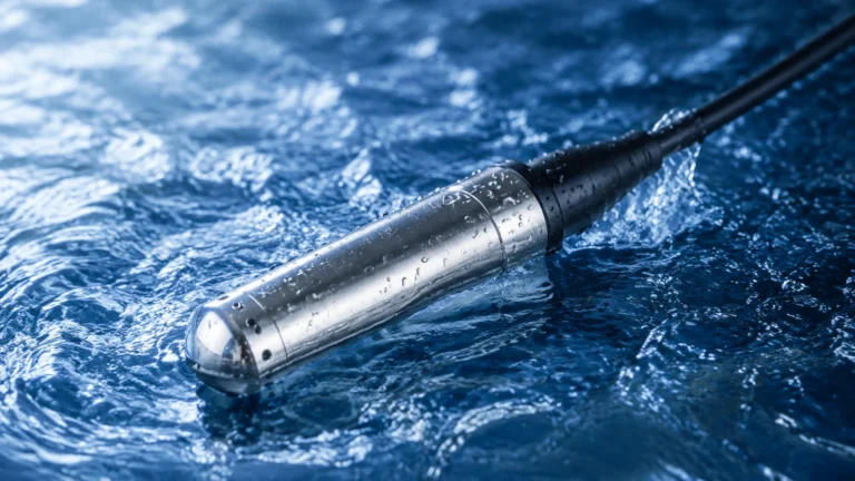
In the field of industrial process control, the AST 35 series represents a specialized class of hydrostatic level transmitters designed for submersible liquid level measurement. These instruments are engineered to provide continuous level monitoring in environments ranging from deep groundwater wells and reservoirs to industrial wastewater tanks and fuel storage facilities. Understanding the technical nuances of the AST 35 is essential for engineers and procurement professionals who require high-accuracy data in challenging submerged conditions.
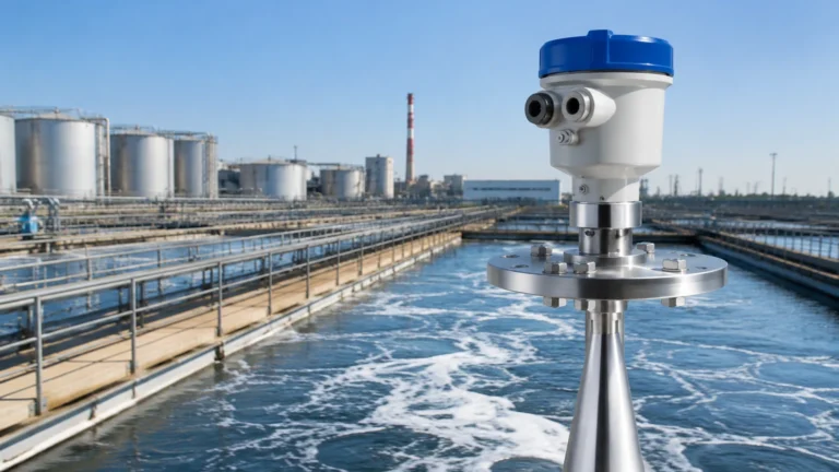
As a professional manufacturer of industrial level measurement instruments, Welk provides a comprehensive range of solutions, including radar level meters and ultrasonic sensors. However, for applications where top-down non-contact measurement is impractical—such as in narrow boreholes or deep underground sumps—the AST 35 hydrostatic approach remains a primary choice for reliability and cost-effectiveness. For a broader overview of available technologies, users can refer to the Main Page of our product catalog.
Measurement Principles of the AST 35
The AST 35 operates on the principle of hydrostatic pressure measurement. This method is based on the physical law that the pressure at a specific point within a static liquid is directly proportional to the height of the liquid column above that point, multiplied by the liquid's density and the local gravitational constant.
The Hydrostatic Equation
The fundamental formula used by the AST 35 is:
P = ρ × g × h
Where:
* P is the hydrostatic pressure (measured in Pascals or Bar).
* ρ (rho) is the density of the liquid (kg/m³).
* g is the acceleration due to gravity (approximately 9.81 m/s²).
* h is the height of the liquid column (meters).
Because gravity and density (assuming a stable temperature) are constants, the pressure measured by the sensor at the bottom of a tank or well can be converted directly into a linear level reading. The AST 35 utilizes a sensitive piezoresistive silicon or ceramic diaphragm to detect this pressure. As the liquid level rises, the pressure on the diaphragm increases, causing a proportional change in the electrical resistance of the sensor element. This change is then conditioned by internal electronics into a standard industrial output signal, typically 4-20mA or a digital RS485 Modbus signal.
Atmospheric Pressure Compensation
A critical feature of the AST 35 is its ability to compensate for changes in atmospheric pressure. Since the sensor is submerged, it is subjected to both the weight of the liquid and the weight of the atmosphere pressing down on the liquid's surface. To ensure the reading reflects only the liquid level, the AST 35 includes a vented cable. This cable contains a small capillary tube that allows the internal side of the sensor diaphragm to "breathe" and remain at the same pressure as the atmosphere, effectively canceling out barometric fluctuations.
Technical Specifications and Features
The AST 35 is designed for durability in long-term immersion. Typical construction materials and performance parameters include:
* Housing Material: Usually 316L Stainless Steel for standard water applications, with options for Titanium or Hastelloy in corrosive chemical environments.
* Accuracy: Standard units offer ±0.5% Full Scale (FS), with high-precision versions reaching ±0.1% or ±0.25% FS.
* Measurement Ranges: Capable of measuring levels from as shallow as 1 meter (3.28 ft) up to 200 meters (656 ft) or more.
* Ingress Protection: IP68 rated, ensuring the internal electronics remain hermetically sealed against moisture ingress even at high pressures.
* Operating Temperature: Typically rated from -20°C to +80°C (-4°F to 176°F), though specialized high-temperature versions are available for industrial process tanks.
Practical Selection Table for AST 35 Configurations
When selecting an AST 35 unit, the application environment dictates the necessary specifications. The following table provides a guideline for matching sensor features to common industrial scenarios.
| Application Type | Recommended Material | Cable Type | Key Requirement |
| :— | :— | :— | :— |
| Potable Water / Reservoirs | 316L Stainless Steel | Polyurethane (PUR) | NSF or food-grade certification |
| Wastewater / Sewage | 316L SS with Clog-resistant nose | PE or PVC | Large sensing diaphragm to prevent fouling |
| Chemical Storage (Acids) | PVDF or Titanium | Teflon (FEP) | Chemical compatibility with the housing and cable |
| Deep Boreholes | 316L Stainless Steel | PE with Kevlar reinforcement | High tensile strength for long cable runs |
| Fuel / Oil Tanks | 316L Stainless Steel | Oil-resistant PUR | Explosion-proof (Ex ia) certification |
Installation Considerations
Proper installation is paramount to the longevity and accuracy of an AST 35 transmitter. Because these sensors are suspended by their signal cables, mechanical stress and environmental factors must be managed carefully.
1. Cable Suspension and Anchoring
The cable of the AST 35 serves two purposes: transmitting the signal and supporting the weight of the sensor. In deep applications, the weight of the cable itself can cause stretching. It is recommended to use a cable clamp or grip at the top of the well to secure the unit without pinching the internal vent tube. If the liquid is turbulent (e.g., near an agitator or inlet pipe), the sensor should be housed within a stilling well—a perforated pipe that dampens wave action while allowing the liquid level to equalize.
2. The Venting System
The capillary tube inside the cable must remain unobstructed. If moisture enters the vent tube, it can lead to sensor drift or permanent damage to the electronics. Engineers should use a vented junction box at the termination point. These boxes often contain a desiccant cartridge to strip moisture from the air before it enters the capillary tube.
3. Avoiding Electrical Interference
In industrial automation settings, signal cables often run alongside high-voltage power lines. To prevent electromagnetic interference (EMI), the AST 35 cable should be shielded, and the shield should be grounded at the controller side (PLC or DCS), not at the sensor side, to avoid ground loops.

Limitations and Operational Boundaries
While the AST 35 is a versatile tool, it is not suitable for every application. Engineers must recognize its limitations to avoid measurement errors.
* Density Sensitivity: Since the measurement is based on pressure, any change in the liquid's density (caused by temperature shifts or concentration changes) will result in an error. For example, if a sensor is calibrated for water (1000 kg/m³) but used in a brine solution (1200 kg/m³), the level reading will be 20% higher than the actual height.
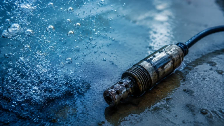
* Mechanical Fouling: In liquids with high solids content or those prone to crystallization, the small pressure port of a standard AST 35 can become clogged. In these cases, a flush-diaphragm version or a non-contact ultrasonic sensor might be more appropriate.
* Pressure Spikes: The AST 35 should not be installed in pipes where water hammer or significant surges occur, as the instantaneous pressure can exceed the sensor's burst pressure rating.
Maintenance and Calibration
The AST 35 is generally low-maintenance due to its solid-state design. However, periodic checks are recommended:
1. Cleaning: If used in wastewater, the sensor head should be inspected every 6 to 12 months for buildup of algae, silt, or grease.
2. Zero-Point Verification: Over several years, sensors may experience "zero drift." This can be checked by pulling the sensor out of the liquid and verifying that the output returns to 4.00mA (for a 4-20mA system).
3. Desiccant Replacement: If a vented junction box is used, the desiccant color should be monitored. Once it changes from blue to pink (or orange to green, depending on the type), it must be replaced to protect the vent tube.
Frequently Asked Questions (FAQs)
Q: Can the AST 35 be used in pressurized tanks?
A: Standard AST 35 units are designed for vented (atmospheric) tanks. In a pressurized tank, the sensor would measure both the liquid head and the gas pressure above it. For pressurized vessels, a differential pressure (DP) transmitter is usually required unless the AST 35 is specifically modified for high-pressure compensation.
Q: How do I calculate the pressure range I need?
A: To determine the required bar rating, multiply the maximum depth in meters by 0.098. For example, a 10-meter tank requires a sensor rated for at least 0.98 bar. It is common practice to select a sensor with a range slightly higher than the maximum depth (e.g., a 1.0 bar or 1.6 bar sensor for a 10m tank).
Q: What is the maximum cable length for an AST 35?
A: Using a 4-20mA current loop, the signal can typically travel up to 1,000 meters (3,280 ft) without significant degradation, provided the power supply voltage is sufficient to overcome the loop resistance. However, the physical weight of the cable becomes a limiting factor in very deep wells.
Q: Can the sensor be shortened in the field?
A: Shortening the cable is possible but requires extreme care not to block or damage the internal vent tube. It is always preferable to order the exact length required from the manufacturer to ensure factory-sealed integrity.
For more information on selecting the right level measurement technology for your specific industrial application, please visit our Main Page to explore our full range of radar, ultrasonic, and hydrostatic instruments. Welk remains committed to providing accurate and cost-effective solutions for global water treatment and industrial automation needs.