Industrial Radar Sensor
Industrial Radar Sensor
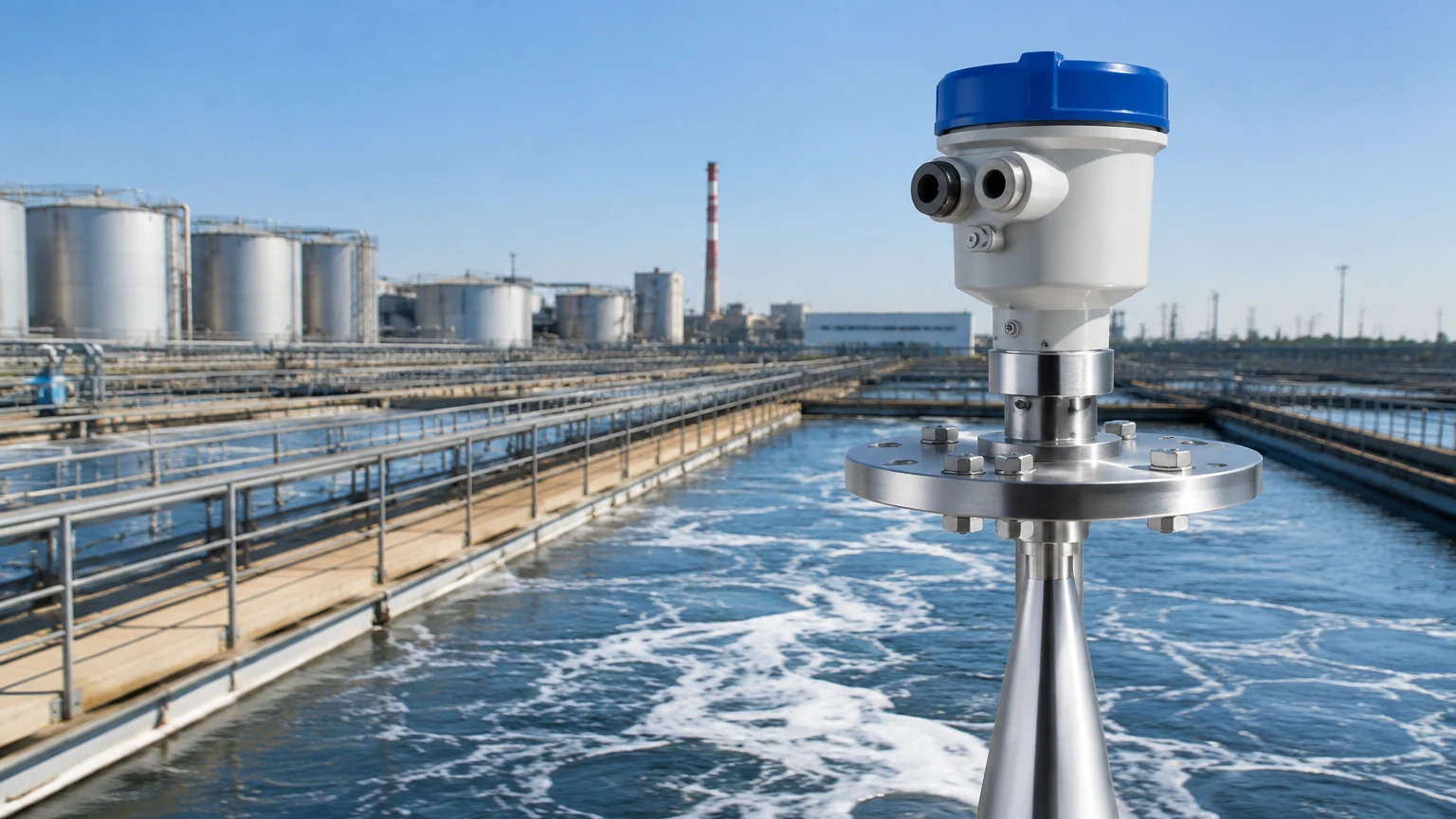
In the landscape of modern process automation, the industrial radar sensor has emerged as a cornerstone technology for non-contact level measurement. These instruments utilize electromagnetic waves to determine the distance to a product surface, providing high-precision data that is essential for inventory management, process control, and safety monitoring. Unlike traditional mechanical or ultrasonic methods, radar technology is largely unaffected by changes in temperature, pressure, or the presence of vapors and dust, making it a versatile solution for industries ranging from chemical processing to water treatment.
Selecting the appropriate industrial radar sensor requires a deep understanding of measurement principles, process conditions, and the physical characteristics of the medium being measured. This guide provides a technical overview of radar technology, practical selection criteria, and installation best practices to ensure reliable performance in demanding industrial environments.
Measurement Principles of Radar Technology
Before evaluating specific models, it is essential to understand how an industrial radar sensor functions. There are two primary methods used in industrial level measurement: Pulse Radar and Frequency Modulated Continuous Wave (FMCW).
Pulse Radar (Time-of-Flight)
Pulse radar sensors emit short microwave pulses toward the target surface. These pulses travel at the speed of light, reflect off the medium, and return to the sensor antenna. The instrument measures the time elapsed between the emission and the reception of the signal. Because the speed of light is constant, the distance is calculated using the formula:
*Distance = (Speed of Light × Time-of-Flight) / 2*
Pulse radar is known for its energy efficiency and is often used in battery-powered or loop-powered applications. However, it may struggle with very low dielectric materials where the reflected signal is weak.
Frequency Modulated Continuous Wave (FMCW)
FMCW radar technology is widely considered the superior choice for high-precision industrial applications. Instead of intermittent pulses, the sensor emits a continuous signal with a frequency that changes linearly over time (a frequency sweep). When the reflected signal is received, it is compared to the signal being emitted at that exact moment. The difference in frequency (the "beat frequency") is directly proportional to the distance to the product surface.
FMCW sensors offer a higher signal-to-noise ratio compared to pulse radar, allowing them to detect even the weakest reflections from materials with low dielectric constants. This makes them ideal for measuring hydrocarbons, powders, and liquids in turbulent conditions.
Types of Industrial Radar Sensors
Industrial radar sensors are generally categorized by their frequency and whether they are contact or non-contact instruments.
Non-Contact Radar
Non-contact radar sensors are mounted at the top of a vessel and do not touch the medium. They are divided into frequency bands that dictate their performance characteristics:
* 80GHz Radar: The current industry standard for high-precision measurement. The high frequency allows for a very narrow beam angle (as low as 3°), which minimizes interference from tank internals like ladders or agitators. It is excellent for narrow tanks and solids.
* 26GHz Radar: A versatile, mid-range frequency used for general-purpose liquid level measurement. It balances cost and performance, making it suitable for larger storage tanks where a wider beam angle is acceptable.
* 6GHz Radar: An older technology with a very wide beam angle. While less common today, it is still used in applications where heavy foam or extreme steam is present, as the longer wavelength can penetrate these obstacles more effectively than higher frequencies.
Guided Wave Radar (GWR)
Guided Wave Radar is a contact-based technology where the microwave pulse travels along a physical probe (cable or rod) submerged in the medium. This method is highly effective for liquids with very low dielectric constants or for interface measurement (e.g., the boundary between oil and water). Because the signal is confined to the probe, it is unaffected by foam, dust, or tank geometry.
Selection Table for Industrial Radar Sensors
Choosing the right sensor involves balancing accuracy, range, and process compatibility. The following table provides a comparison of common configurations.
| Feature | 80GHz Non-Contact | 26GHz Non-Contact | Guided Wave Radar (GWR) |
| :— | :— | :— | :— |
| Measurement Range | Up to 120m | Up to 70m | Up to 30m (Cable) / 6m (Rod) |
| Accuracy | ±1 mm | ±3 mm | ±2 mm |
| Beam Angle | 3° to 8° | 8° to 20° | N/A (Signal follows probe) |
| Dielectric Constant (εr) | ≥ 1.1 | ≥ 1.6 | ≥ 1.4 (Interface ≥ 0.1 difference) |
| Best For | Narrow tanks, solids, high precision | Large liquid storage, corrosive chemicals | Low DK liquids, interface, bypass pipes |
| Process Temperature | -40°C to +200°C+ | -40°C to +150°C | -200°C to +450°C |
| Process Pressure | Vacuum to 40 bar | Vacuum to 40 bar | Vacuum to 400 bar |
For detailed specifications and to Review product options and application support, engineers should consult with a specialized manufacturer like Welk to match the sensor to their specific chemical and physical environment.
Installation Considerations and Best Practices
The reliability of an industrial radar sensor is heavily dependent on correct installation. Even the most advanced 80GHz sensor can fail if it is poorly positioned.
1. Nozzle Geometry
The nozzle on which the radar is mounted should be as short as possible. If the nozzle is too long or narrow, it can create internal reflections (ringing) that mask the true level signal. For non-contact radar, the antenna should ideally extend slightly below the bottom of the nozzle to ensure an unobstructed signal path.
2. Positioning and Clearance
* Distance from Wall: The sensor should be installed at a distance from the tank wall, typically 1/6 of the tank diameter. Mounting too close to the wall can cause signal interference due to the "wall effect."
* Avoiding the Center: In tanks with a conical bottom or where a vortex forms during filling/emptying, mounting the sensor in the exact center can lead to multiple reflections or signal loss. Offset mounting is generally preferred.
* Internal Obstructions: Ensure the signal path is clear of agitators, heating coils, and ladders. If obstructions are unavoidable, high-frequency radar (80GHz) with a narrow beam is required, or the sensor’s software must be used to perform a "false echo suppression" map.
3. Orientation
For liquid applications, the sensor must be mounted perpendicular to the liquid surface. For solids, a swiveling flange is often used to aim the radar beam at the angle of repose of the material, ensuring the strongest possible reflection returns to the antenna.
Limitations and Environmental Challenges
While industrial radar sensors are robust, they are not universal solutions. Certain factors can impede their performance:
* Dielectric Constant (εr): Radar relies on a change in dielectric constant to reflect the signal. Materials with a very low εr (like liquid nitrogen or some dry powders) reflect very little energy. In these cases, Guided Wave Radar or high-sensitivity FMCW units are necessary.
* Heavy Foam: Dense, thick foam can absorb or scatter radar signals. While 6GHz radar or GWR can sometimes penetrate foam, ultrasonic or hydrostatic sensors might be better alternatives if the foam is exceptionally thick and consistent.
* Turbulence: Rapidly moving liquid surfaces can scatter the radar signal. This can be mitigated by using software filtering (damping) or by installing the sensor inside a stilling well or bypass chamber.
* Dust and Condensation: While radar penetrates dust better than ultrasonic sensors, heavy buildup on the antenna can eventually attenuate the signal. Many industrial radar sensors now feature PTFE or ceramic lens covers that resist buildup and are easy to clean.
Frequently Asked Questions (FAQ)
Q: What is the main advantage of radar over ultrasonic level sensors?
A: Radar uses electromagnetic waves, which do not require a medium to travel. This means they work in a vacuum and are unaffected by air temperature, pressure, or gas composition. Ultrasonic sensors use sound waves, which are highly sensitive to these environmental factors.
Q: Can a radar sensor measure the interface between two liquids?
A: Yes, but this is typically achieved using Guided Wave Radar. The signal reflects off the upper liquid layer (e.g., oil) and a portion of the signal continues through to reflect off the lower liquid layer (e.g., water), provided the top layer has a lower dielectric constant.
Q: Does the color or transparency of the liquid affect the measurement?
A: No. Radar is an electromagnetic technology; it is unaffected by the optical properties of the medium. It only cares about the dielectric constant and the surface condition.
Q: How often does an industrial radar sensor need calibration?
A: Because radar sensors have no moving parts and the speed of light is a physical constant, they are extremely stable. Most units do not require routine recalibration after the initial setup, though periodic verification is recommended for safety-critical applications (SIL).
Summary of Next Steps for Project Engineers
When integrating an industrial radar sensor into a facility, the following steps should be confirmed before procurement:
1. Identify the Dielectric Constant: Determine the εr of the medium. If it is below 1.5, consult the manufacturer for a high-sensitivity or GWR solution.
2. Map the Tank Internals: Identify any obstructions that could interfere with the radar beam. This determines whether a narrow-beam 80GHz sensor is required.
3. Check Process Conditions: Confirm maximum temperature and pressure. Ensure the wetted materials of the sensor (e.g., 316L stainless steel, PTFE, Hastelloy) are compatible with the process media.
4. Evaluate Connectivity: Determine if the system requires 4-20mA HART, Modbus, Profibus, or wireless output for integration with the existing PLC or SCADA system.
By following these engineering principles, industrial facilities can implement level measurement solutions that provide long-term accuracy and minimal maintenance requirements. For a comprehensive range of instruments tailored to these needs, visiting the Main Page of a dedicated manufacturer like Welk is the most effective way to begin the technical selection process.