Thermal Dispersion Flow Switch
Thermal Dispersion Flow Switch
In industrial process control, monitoring the presence or absence of flow is critical for equipment protection and process efficiency. The thermal dispersion flow switch has emerged as a preferred solid-state solution for detecting flow in liquids and gases. Unlike traditional mechanical flow switches that rely on moving parts like paddles or pistons, thermal dispersion technology utilizes heat transfer principles to provide a reliable, maintenance-free method of flow detection. This guide provides a comprehensive technical overview of the thermal dispersion flow switch, its measurement principles, selection criteria, and practical installation considerations for engineering professionals.
Measurement Principle of Thermal Dispersion Technology
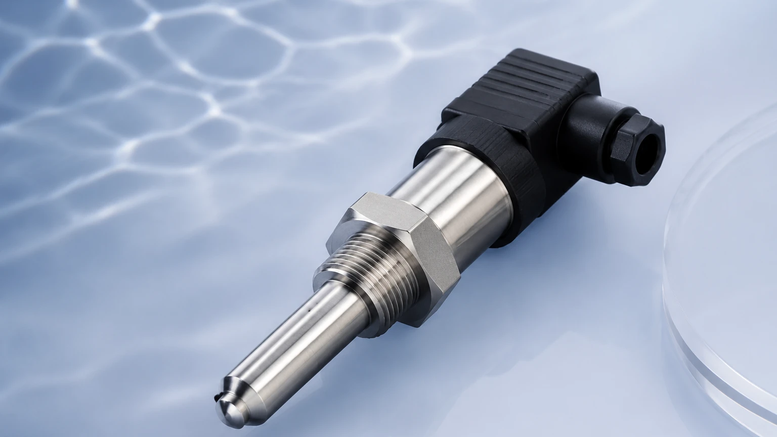
The operation of a thermal dispersion flow switch is based on the physical law of heat transfer. The device typically features a sensing probe containing two temperature sensors (usually Resistance Temperature Detectors or RTDs) embedded within the tip.
The Dual-Sensor Design
One RTD is designated as the "reference sensor" and measures the ambient temperature of the process media. The second RTD is the "active sensor," which is internally heated to a specific temperature above that of the reference sensor. This creates a controlled temperature differential (ΔT) between the two sensors.
Heat Dissipation and Flow Correlation
When the process media is stationary (no-flow condition), the heat dissipation from the active sensor is minimal, and the temperature difference between the two sensors remains at its maximum. As the media begins to flow, the moving fluid carries heat away from the active sensor—a process known as the cooling effect.
As the flow velocity increases, the rate of heat dissipation increases, causing the temperature of the active sensor to drop and narrowing the ΔT. The electronics within the switch monitor this change in temperature differential. Once the cooling effect reaches a pre-defined threshold (the set point), the switch changes its output state (e.g., from open to closed). Because the cooling rate is directly proportional to the mass flow rate and the thermal properties of the fluid, this method allows for highly sensitive detection even at very low flow velocities.
Key Advantages Over Mechanical Switches
Transitioning from mechanical flow switches to thermal dispersion models offers several technical benefits in industrial environments:
1. No Moving Parts: Mechanical switches are prone to wear, fatigue, and jamming due to debris or calcification. Thermal switches are solid-state, significantly reducing the risk of mechanical failure and extending service life.
2. Low Pressure Drop: The probe design is typically a single rod that extends into the pipe, offering minimal resistance to the flow compared to large paddles or restricted orifices.
3. High Sensitivity: Thermal dispersion technology can detect extremely low flow velocities, often down to 0.01 m/s (meters per second) in liquids, which is often below the threshold of mechanical units.
4. Versatility: These switches can be calibrated for a wide range of media, including water, oils, chemicals, and even gases, provided the thermal conductivity of the media is known.
5. Multi-Functionality: Many modern thermal dispersion switches also include integrated temperature monitoring, allowing the device to serve as both a flow and temperature switch.
Technical Selection Criteria
When selecting a thermal dispersion flow switch for a specific application, engineers must evaluate several parameters to ensure long-term accuracy and reliability. For comprehensive technical specifications and product comparisons, engineers can Review product options and application support to match the instrument to their specific process conditions.
Media Compatibility and Properties
The thermal conductivity and viscosity of the fluid are the primary factors affecting performance. High-viscosity fluids may require different calibration settings than water-like liquids. Additionally, the wetted materials of the probe (typically 316L Stainless Steel, Hastelloy, or PTFE-coated metals) must be chemically compatible with the process media to prevent corrosion.
Operating Temperature and Pressure
Standard thermal flow switches are designed for temperatures up to 80°C or 100°C, but high-temperature versions can handle processes exceeding 200°C. Pressure ratings must also be verified, with many industrial probes rated for 100 bar (approx. 1450 psi) or higher.
Pipe Diameter and Probe Length
The probe must be long enough to reach the area of maximum flow velocity (typically the center of the pipe) but not so long that it causes structural vibration or excessive turbulence. For larger pipes (e.g., >200 mm), adjustable immersion lengths are often required.
Selection Summary Table
| Parameter | Consideration | Typical Range/Value |
| :— | :— | :— |
| Media State | Liquid or Gas | Liquid preferred for higher sensitivity |
| Flow Velocity Range | Minimum/Maximum detection | 0.01 m/s to 3 m/s (Liquids) |
| Process Connection | Threaded, Flanged, or Tri-clamp | G1/2", NPT, DN25 Flange |
| Output Type | Relay, PNP/NPN, or 4-20mA | Relay (SPDT) is most common for alarm loops |
| Response Time | Time to trigger after flow change | 2 to 10 seconds (standard) |
| Wetted Materials | Chemical resistance | 316L SS, Titanium, Tantalum |
Installation Considerations and Best Practices
Proper installation is paramount to the performance of a thermal dispersion flow switch. Turbulence and air pockets are the most common causes of false readings.
Straight Pipe Requirements
To ensure a stable flow profile, the switch should be installed in a section of straight pipe. A general rule of thumb is to have at least 5D (five times the pipe diameter) of straight pipe upstream of the sensor and 3D downstream. If there are pumps or valves immediately upstream, the required straight run may increase to 10D or more.
Orientation and Positioning
* Horizontal Pipes: The switch should ideally be installed from the side of the pipe. Mounting from the top can lead to errors if air bubbles collect at the high point. Mounting from the bottom can lead to errors if sediment or sludge settles on the probe tip, insulating it from the flow.
* Vertical Pipes: Flow should ideally be in an upward direction. This ensures that the pipe is always completely full of liquid. If downward flow is necessary, the flow rate must be high enough to keep the pipe full, as any air gap will cause the switch to indicate a "no-flow" condition.
Insertion Depth
The sensing tip must be fully immersed in the moving fluid. In smaller pipes (less than 50 mm), the tip should be positioned near the center. In larger conduits, ensure the probe extends past any boundary layer turbulence near the pipe wall.
Limitations and Potential Risks
While highly reliable, thermal dispersion flow switches have specific limitations that must be addressed during the design phase:
* Coating and Scaling: If the process media tends to leave deposits (e.g., calcium buildup or heavy oils), a layer of insulation can form on the probe. This reduces the heat transfer efficiency and can cause the switch to become sluggish or fail to detect flow changes. Regular inspection or the use of polished/non-stick probes is recommended in these environments.
* Aerated Liquids: Large air bubbles or significant entrained gas in a liquid stream can cause erratic switching, as the thermal conductivity of gas is significantly lower than that of liquid.
* Rapid Temperature Swings: Because the measurement relies on a temperature differential, sudden and extreme changes in the ambient media temperature (thermal shocks) can cause temporary false alarms while the reference sensor stabilizes.
Maintenance and Troubleshooting
Because they lack moving parts, maintenance is minimal. However, if the switch fails to trigger, the following steps should be taken:
1. Check for Fouling: Remove the probe and inspect the tip for any coating or debris.
2. Verify Set Point: Ensure the potentiometer or digital set point has not been bumped or incorrectly adjusted for the current media.
3. Power Supply Check: Confirm that the input voltage matches the device specifications (typically 24V DC or 230V AC).
4. Media Change: If the process fluid has changed (e.g., switching from water to a water-glycol mix), the device will likely require recalibration due to the change in thermal conductivity.
Frequently Asked Questions (FAQ)
Q: Can a thermal dispersion flow switch be used for both liquids and gases?
A: Yes, but the calibration is different. Gases have much lower thermal conductivity than liquids, so the internal heating and sensitivity settings must be adjusted accordingly. Many manufacturers offer specific models optimized for gas flow.
Q: How does viscosity affect the switch?
A: Higher viscosity fluids move more slowly and have different heat transfer rates. While the switch will still function, the set point must be calibrated specifically for the viscous media to ensure accuracy.
Q: Is the response time adjustable?
A: In many digital models, a damping or delay function can be programmed to prevent the switch from "chattering" if the flow is turbulent or pulsating.
Q: What is the typical lifespan of these sensors?
A: In non-corrosive and non-scaling applications, thermal dispersion switches often last 10 years or more due to the absence of mechanical wear.
Conclusion
The thermal dispersion flow switch represents a robust, high-performance solution for modern industrial flow monitoring. By understanding the underlying thermal principles and adhering to strict installation guidelines regarding pipe geometry and media compatibility, engineers can implement a flow detection system that minimizes downtime and protects critical infrastructure. For those seeking reliable level and flow instrumentation, the Main Page of Welk provides access to a broad portfolio of industrial measurement solutions tailored for water treatment, chemical processing, and automation sectors.