Co2 Capture System
Co2 Capture System
In the global effort to mitigate industrial emissions, the implementation of a robust co2 capture system has become a cornerstone for sectors such as power generation, cement manufacturing, and steel production. These systems are designed to isolate carbon dioxide from industrial flue gases or process streams before it is released into the atmosphere. For engineers and plant operators, the success of carbon capture, utilization, and storage (CCUS) projects depends not only on the chemical efficiency of the solvents used but also on the precision of the instrumentation governing the process. Reliable level measurement is critical for maintaining the mass balance and safety of these complex chemical loops.
Introduction to Industrial CO2 Capture Systems
A co2 capture system typically operates through one of three primary pathways: post-combustion, pre-combustion, or oxy-fuel combustion. Post-combustion capture is the most common for existing power plants, utilizing chemical solvents like amines to scrub CO2 from exhaust gases. Pre-combustion capture involves gasifying fuel to produce a mixture of hydrogen and CO2, while oxy-fuel combustion uses pure oxygen for burning, resulting in a flue gas composed almost entirely of CO2 and water vapor.
Regardless of the method, the process involves multiple stages of separation, compression, and storage. Throughout these stages, liquid levels in absorbers, regenerators, flash tanks, and storage vessels must be monitored with high accuracy. Failure to maintain correct levels can lead to solvent carryover, pump cavitation, or hazardous overfill conditions. For a detailed look at the instrumentation required for these applications, professionals often consult the Main Page of specialized equipment providers to evaluate technical specifications.
Core Technologies in Carbon Sequestration
To understand the instrumentation requirements, one must first understand the environment within a co2 capture system. The most prevalent technology, amine scrubbing, involves a cycle where a "lean" solvent enters an absorber column to react with CO2. The resulting "rich" solvent is then pumped to a stripper (regenerator) where heat is applied to release the CO2, returning the solvent to its lean state.
This cycle involves varying temperatures (typically 40°C to 150°C) and pressures. Furthermore, the storage of captured CO2 requires liquefaction, which occurs at high pressures (often exceeding 20 bar) and low temperatures (down to -50°C). Each of these environments dictates specific requirements for level sensors, which must withstand corrosive chemicals, foaming, and cryogenic conditions.
Level Measurement Principles in CCS Applications
Before selecting instrumentation for a co2 capture system, it is essential to understand the underlying measurement principles. Each technology offers distinct advantages depending on the physical properties of the media.
1. Radar Level Measurement (FMCW and GWR)
Radar technology is the gold standard for many CCUS applications.
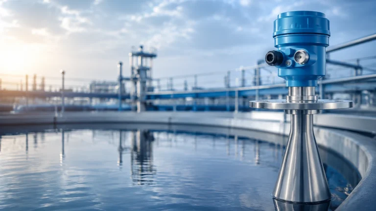
* Non-Contact Radar (FMCW): Frequency Modulated Continuous Wave radar emits a continuous signal with a varying frequency. The difference between the transmitted and received frequency is proportional to the distance. In a co2 capture system, 80GHz radar is preferred because its narrow beam angle avoids internal obstructions in tall absorber columns.
* Guided Wave Radar (GWR): This utilizes Time Domain Reflectometry (TDR). A high-frequency electromagnetic pulse is guided along a probe. When it hits the liquid surface, a portion of the energy is reflected back. GWR is particularly effective for low-dielectric liquids like liquid CO2, as the probe concentrates the signal.
2. Ultrasonic Level Sensors
Ultrasonic sensors measure the time of flight of sound waves. While cost-effective, they are generally limited in a co2 capture system because the speed of sound is highly dependent on the gas composition and temperature. In an environment with fluctuating CO2 concentrations and vapors, ultrasonic accuracy can degrade significantly.
3. Hydrostatic Level Transmitters
This principle relies on the relationship between pressure and liquid height ($P = \rho \cdot g \cdot h$). By measuring the pressure at the bottom of a tank and compensating for the headspace pressure (using differential pressure), the level can be calculated. This is a reliable method for solvent tanks where the density is well-known and stable.
4. Magnetic Level Gauges (MLG)
MLGs utilize a float containing a magnet that moves with the liquid level inside a bypass chamber. This magnet flips external flags for visual indication and can be paired with a magnetostrictive transmitter for continuous electronic output. They are favored for high-pressure CO2 storage because they provide a physical, leak-proof barrier between the process and the observer.
Selecting Level Instrumentation for CO2 Capture
Selecting the right sensor for a co2 capture system requires a comparison of process conditions. The following table provides a general guideline for technology selection based on common media found in these systems.
| Process Media | Recommended Technology | Key Reason | Temperature/Pressure Considerations |
| :— | :— | :— | :— |
| Amine Solvent (Lean/Rich) | Guided Wave Radar (GWR) | Handles foam and turbulence well. | Up to 150°C; atmospheric to moderate pressure. |
| Liquid CO2 (Storage) | Non-Contact Radar (80GHz) | No moving parts; high accuracy at high pressure. | -50°C to +30°C; 20-60 bar. |
| Condensate/Water | Hydrostatic Pressure | Cost-effective and reliable. | Ambient to 80°C. |
| Acid Gas/Flue Gas | Ultrasonic (Point Level) | Non-contact for high-level alarms. | High moisture content may affect accuracy. |
| Flash Tanks | Magnetic Level Gauge | Visual safety and high-pressure rating. | Rapid pressure changes. |
Installation and Engineering Considerations
Proper installation is as vital as technology selection in a co2 capture system. Engineering teams should adhere to the following guidelines to ensure long-term reliability:
* Nozzle Geometry: For non-contact radar, the nozzle height should be minimized to prevent signal interference. If long nozzles are necessary, the sensor must be configured to ignore the nozzle reflection.
* Stillwells and Bypass Chambers: In absorbers where heavy foaming or turbulence occurs, installing a GWR or a displacement-type sensor inside a stillwell can provide a stable surface for measurement.
* Material Compatibility: Amine solutions can be corrosive to certain metals. 316L stainless steel is typically the minimum requirement, while some high-temperature stripper applications may require Hastelloy or PTFE coatings.
* Pressure Ratings: For liquid CO2 storage, the instrument flange must be rated for the maximum allowable working pressure (MAWP) of the vessel, often Class 300 or higher.
Operational Challenges and Limitations
While modern instrumentation is highly advanced, a co2 capture system presents unique challenges that can limit sensor performance:
1. Foaming: Chemical absorption processes are prone to foaming. Foam can absorb radar signals or create false echoes. Using 80GHz radar with advanced signal processing or GWR with a coaxial probe can mitigate this.
2. Dielectric Constant ($\\varepsilon_r$): Pure liquid CO2 has a very low dielectric constant ($\\varepsilon_r \\approx 1.6$). This makes it difficult for standard radar sensors to detect the surface. High-sensitivity radar units or GWR are necessary to ensure the signal reflection is strong enough for a reliable reading.
3. Supercritical Transitions: Near the critical point of CO2 (31.1°C, 73.8 bar), the distinction between liquid and gas phases becomes blurred. Level measurement becomes physically impossible in the supercritical phase, so systems must be designed to operate within sub-critical ranges for level monitoring.
4. Vapor Space Compensation: In high-pressure gas phases, the speed of radar signals can slightly decrease. For ultra-precise measurements in CO2 tanks, vapor space compensation (using a reference target) may be required.
Frequently Asked Questions (FAQs)
Q: Can I use ultrasonic sensors for liquid CO2 level measurement?
A: It is not recommended. The high-pressure CO2 vapor above the liquid significantly alters the speed of sound, leading to massive measurement errors unless the gas composition and temperature are perfectly constant and compensated for.
Q: How does foaming in the amine absorber affect radar sensors?
A: Foam can either scatter the radar signal or be detected as the liquid level. Using a Guided Wave Radar (GWR) with a probe that pierces through the foam to reach the liquid surface is usually the most effective solution.
Q: What is the best way to monitor level in a high-pressure CO2 transport vessel?
A: Magnetic Level Gauges paired with magnetostrictive transmitters are often preferred for transport and storage because they offer a robust mechanical solution that remains functional even during power failures.
Q: Are there specific maintenance requirements for level sensors in a co2 capture system?
A: Yes. Sensors in amine service should be checked periodically for chemical buildup or scaling on the probes. Non-contact sensors should be inspected for condensation on the antenna, although many modern 80GHz units feature drip-off designs to prevent this.
For engineers looking to integrate these technologies into a new or existing co2 capture system, reviewing the Main Page of an experienced manufacturer is the first step in ensuring that the selected instrumentation meets the rigorous demands of carbon sequestration. Accurate level control is not just a matter of process efficiency; it is a fundamental requirement for the safety and scalability of global decarbonization efforts.