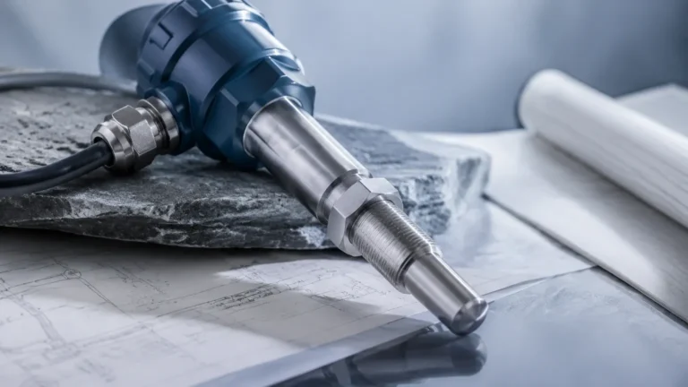
Thermal Dispersion Flow Switches
Thermal Dispersion Flow Switches
In modern industrial automation, the reliable detection of fluid movement is critical for protecting equipment and ensuring process consistency. Thermal dispersion flow switches have emerged as a preferred solution for many engineers due to their solid-state design and high sensitivity. Unlike traditional mechanical flow switches that rely on paddles or pistons, thermal dispersion technology utilizes the principles of heat transfer to monitor flow velocity, offering a maintenance-free alternative for demanding environments.
This guide provides a technical overview of thermal dispersion flow switches, explaining their operational physics, selection criteria, and practical installation requirements to help process engineers integrate them effectively into their systems.
Measurement Principle of Thermal Dispersion
The operation of thermal dispersion flow switches is based on the physical law of thermal conduction and convection. The sensor probe typically contains two Resistance Temperature Detectors (RTDs) housed within high-quality stainless steel or alloy thermowells.
1. The Reference Sensor: One RTD measures the actual temperature of the process medium (liquid or gas). This provides a baseline temperature for the system.
2. The Active (Heated) Sensor: The second RTD is internally heated to a constant power level, creating a temperature differential ($\Delta T$) between itself and the reference sensor.
When the fluid is stationary (zero flow), the heat remains concentrated around the active sensor, resulting in a maximum temperature difference between the two RTDs. As the fluid begins to move, it carries heat away from the active sensor—a process known as heat dissipation or "dispersion." The rate of heat loss is directly proportional to the mass flow velocity of the fluid.
Electronic circuits within the switch monitor this $\Delta T$. When the flow velocity reaches a user-defined setpoint, the temperature difference decreases to a specific threshold, triggering the switch output (typically a relay or transistor signal). Because this method measures the cooling effect of the fluid, it is inherently related to the mass flow and thermal properties of the medium, making it highly sensitive even at very low flow rates.
Key Advantages of Solid-State Flow Detection
Thermal dispersion flow switches offer several distinct advantages over mechanical alternatives like paddle-wheel or spring-loaded switches:
* No Moving Parts: The absence of mechanical linkages, springs, or paddles means there is no wear and tear, significantly reducing the risk of mechanical failure and the need for periodic maintenance.
* Low Pressure Drop: The probe design is non-intrusive or minimally intrusive, causing negligible obstruction to the flow path. This is vital for maintaining system efficiency in low-pressure applications.
* High Sensitivity: These switches can detect extremely low flow velocities, often down to 0.01 meters per second (m/s) in liquids, which is often below the threshold of mechanical devices.
* Versatility: The same sensor can often be used for both liquids and gases, provided the electronics are calibrated for the specific thermal conductivity of the medium.
* Durability: Constructed from robust materials like 316L stainless steel, Hastelloy, or Monel, they are highly resistant to corrosion and can withstand high-pressure environments.
Selection Criteria for Industrial Applications
Choosing the correct thermal dispersion flow switch requires a detailed understanding of the process conditions. Engineers should evaluate the following parameters before procurement:
Media Compatibility
The thermal conductivity of the fluid is the most critical factor. While most switches are factory-calibrated for water or air, specialized calibration may be required for oils, glycol mixes, or corrosive chemicals. Ensure the wetted materials are compatible with the chemical composition of the fluid to prevent premature probe failure.
Temperature and Pressure
Standard thermal switches typically operate up to 100°C (212°F) and 100 bar (1450 psi). For high-temperature applications, such as steam condensate or hot oil loops, specialized high-temperature versions with remote electronics may be necessary to protect the internal circuitry from heat damage.
Pipe Size and Insertion Depth
For the switch to function accurately, the sensor tip must be positioned in the area of the pipe where the flow is most stable—typically the center of the pipe. For large diameter pipes, adjustable insertion lengths are required. For small pipes (less than DN25), inline blocks are often used instead of insertion probes.
Selection Summary Table
| Parameter | Liquid Applications | Gas Applications |
| :— | :— | :— |
| Flow Range (Typical) | 0.01 to 3.0 m/s | 0.1 to 50 m/s |
| Response Time | 1 to 10 seconds | 2 to 30 seconds |
| Wetted Materials | 316L SS, Hastelloy, Titanium | 316L SS, Teflon coated |
| Standard Connection | G1/2", 1/2" NPT, Flanged | G1/2", 1/2" NPT, Flanged |
| Output Options | Relay, PNP/NPN, 4-20mA (optional) | Relay, PNP/NPN, 4-20mA (optional) |
Installation Considerations and Best Practices
Proper installation is paramount to the reliability of thermal dispersion flow switches. Incorrect positioning can lead to false alarms or a failure to detect flow.
Straight Pipe Requirements
To ensure a stable flow profile, the switch should be installed in a section of straight pipe. A general rule of thumb is to provide at least 5 diameters (5D) of straight pipe upstream of the sensor and 3 diameters (3D) downstream. If the installation is near a pump or a high-turbulence valve, these distances should be increased.
Orientation and Air Pockets
* Horizontal Pipes: The switch should ideally be installed on the side of the pipe. Mounting on the top can lead to errors if air pockets or bubbles collect around the probe. Mounting on the bottom can lead to errors if sediment or sludge builds up around the sensor tip.
* Vertical Pipes: For vertical installations, the flow direction should always be upward. This ensures the pipe remains full of liquid, preventing "dry run" false signals that occur when a pipe is only partially filled.
Probe Immersion
The active part of the probe (the tip) must be fully immersed in the fluid at all times. If the probe is only partially submerged, the heat dissipation will be inconsistent, leading to erratic switching behavior.

Limitations and Common Risks
While highly reliable, thermal dispersion flow switches are not universal solutions. Users should be aware of the following limitations:
1. Coating and Fouling: If the process medium is prone to scaling, calcification, or heavy coating (e.g., wastewater with high grease content), a layer of insulation can build up on the probe tip. This insulation slows down heat transfer, causing the switch to become sluggish or fail to detect flow changes. Regular cleaning is required in these environments.
2. Rapid Temperature Swings: Because the switch relies on a temperature differential, sudden and extreme changes in the process temperature (thermal shocks) can cause temporary false switching while the reference sensor stabilizes.
3. Viscosity Changes: Significant changes in fluid viscosity (e.g., oil being heated) will change the thermal dispersion rate. If the viscosity varies widely, the setpoint may need to be adjusted to compensate for the different cooling characteristics.
Industrial Applications
Thermal dispersion flow switches are widely utilized across various sectors where flow confirmation is essential for safety and efficiency:
* Pump Protection: Preventing pumps from running dry or operating against a closed valve (dead-heading), which can lead to overheating and seal failure.
* Cooling Systems: Monitoring the flow of coolant to heat exchangers, lasers, or induction furnaces to prevent equipment damage.
* Water Treatment: Confirming chemical dosing flow and monitoring filter backwash cycles.
* HVAC Systems: Detecting airflow in ducts to ensure fans are operational before activating heating or cooling coils.
For engineers seeking comprehensive measurement solutions, integrating these switches alongside advanced level instrumentation ensures total process control. For more information on professional-grade industrial measurement tools, visit the Welk Main Page.
Frequently Asked Questions (FAQ)
Q: Can thermal dispersion flow switches be used for hazardous areas?
A: Yes, many models are available with ATEX or IECEx certifications for use in explosive atmospheres, typically featuring explosion-proof housings or intrinsically safe electronics.
Q: How do I calibrate the setpoint?
A: Most modern switches feature a "teach-in" button or a potentiometer. To calibrate, you typically establish the desired minimum flow in the process and then adjust the switch until the output status changes. Some digital models allow for precise velocity setpoints via a display.
Q: Do these switches require frequent recalibration?
A: No. Because they have no moving parts to wear down, the calibration remains stable over long periods. Recalibration is generally only necessary if the process fluid or the required flow setpoint changes.
Q: What happens if the power to the switch fails?
A: Most thermal flow switches are designed to be "fail-safe." Depending on the wiring (Normally Open vs. Normally Closed), the system can be configured to signal a "no-flow" state if power is lost, ensuring the safety of the downstream equipment.
By understanding the thermal dispersion principle and following strict installation guidelines, industrial operators can achieve highly reliable flow monitoring with minimal maintenance overhead. Whether protecting a high-value pump or ensuring the safety of a chemical process, these switches provide a robust solution for modern engineering challenges.