Tank Level Control
Tank Level Control
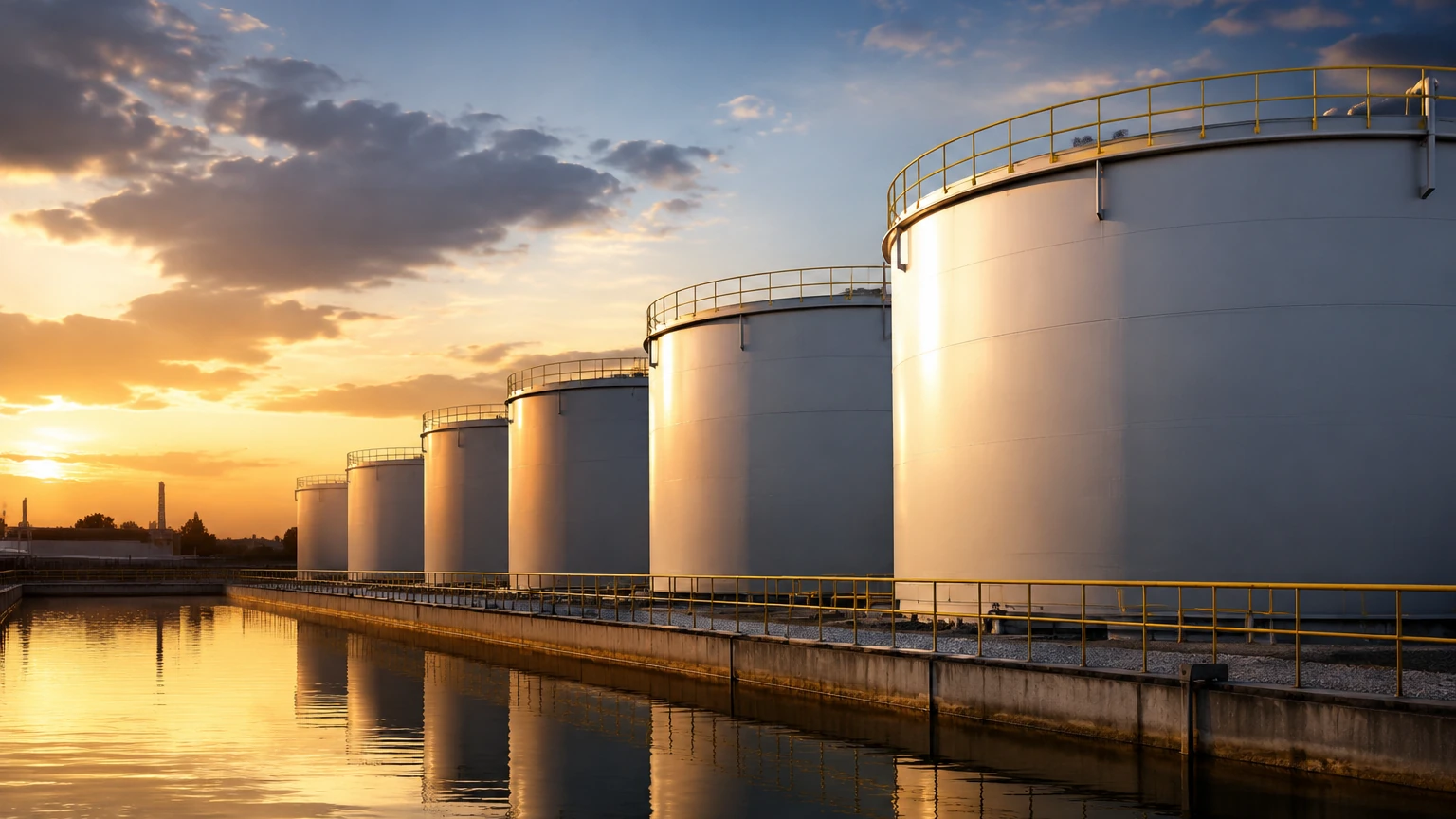
Tank level control is a fundamental requirement in modern industrial automation, ensuring that liquids or solids within a vessel remain within specified limits to maintain process efficiency, safety, and inventory accuracy. Whether managing water treatment facilities, chemical processing plants, or oil and gas storage, the ability to monitor and regulate levels prevents costly overflows, pump cavitation, and production downtime. Achieving effective tank level control requires a deep understanding of measurement principles, the integration of sensors with control logic, and the selection of the appropriate technology for specific environmental conditions.
Fundamental Measurement Principles
Before implementing a control strategy, engineers must select the sensing technology that best fits the physical properties of the medium and the vessel. Industrial level measurement generally falls into two categories: continuous measurement and point level detection.
Radar Level Measurement (Non-Contact)
Radar level meters utilize high-frequency electromagnetic waves, typically in the microwave range. These waves are emitted from an antenna, reflect off the surface of the material in the tank, and return to the sensor. The device calculates the distance based on the time-of-flight or frequency shift (FMCW). Because radar waves do not require a physical medium for travel, they are unaffected by vacuum, high pressure, or extreme temperatures. This makes them ideal for volatile chemicals and high-precision applications.
Ultrasonic Level Measurement
Ultrasonic sensors function by emitting high-frequency sound pulses. The time taken for the echo to return from the surface is used to determine the distance. While cost-effective and easy to install, ultrasonic waves are mechanical and can be influenced by air temperature, heavy foam, or dust. Most modern ultrasonic sensors include temperature compensation to maintain accuracy across varying ambient conditions.
Hydrostatic Level Measurement
Hydrostatic transmitters measure the pressure exerted by a liquid column at the bottom of a tank. Based on the principle that pressure is proportional to the height of the liquid and its density ($P = \rho gh$), these sensors provide a reliable continuous signal. They are commonly used in vented tanks and deep wells, though they require recalibration if the liquid density changes significantly.
Magnetic Level Gauges
Magnetic level gauges utilize a float containing a permanent magnet that moves with the liquid level inside a bypass chamber. Outside the chamber, a series of magnetic flags or a transmitter responds to the float's position. This provides both a local visual indication and a remote electrical signal, making it a robust choice for high-pressure or high-temperature boiler applications.
Level Switches (Point Level)
Level switches are used for discrete control, such as high-level alarms or low-level pump protection. Technologies include tuning forks (vibration), float switches, and capacitive sensors. These devices do not provide a continuous level reading but are critical for redundant safety systems in any tank level control architecture.
Strategies for Tank Level Control
Once a reliable measurement signal is established, it must be integrated into a control loop. The complexity of the control strategy depends on the process requirements.
On/Off Control
This is the simplest form of tank level control. When the level reaches a low setpoint, a pump or valve is activated to fill the tank. Once the high setpoint is reached, the action is stopped. This method is common in basic water storage but can lead to frequent cycling of equipment, increasing mechanical wear.
Continuous PID Control
For processes requiring a steady state, Proportional-Integral-Derivative (PID) control is used. The controller receives a continuous signal from a sensor and adjusts a variable frequency drive (VFD) or a modulating valve to match the inflow or outflow with the setpoint. This minimizes fluctuations and is essential for chemical dosing or reactor feed systems.
Integration with PLC and SCADA
In large-scale industrial environments, sensors are connected to a Programmable Logic Controller (PLC). The PLC processes the data and communicates with a Supervisory Control and Data Acquisition (SCADA) system. This allows operators to monitor real-time trends, manage alarms, and log data for regulatory compliance. For comprehensive hardware options, engineers can Review product options and application support to ensure compatibility with existing control infrastructures.
Selection Criteria for Level Instrumentation
Choosing the wrong sensor can lead to signal loss or premature failure. Engineers should evaluate the following criteria before finalizing a design:
1. Media Characteristics: Is the material corrosive, viscous, or prone to foaming? Does it have a low dielectric constant (relevant for radar)?
2. Tank Geometry: Are there internal obstructions like agitators, heating coils, or baffles? Narrow tanks may require guided wave radar rather than through-air radar.
3. Process Conditions: What are the maximum operating pressures (in Bar) and temperatures (in Celsius)?
4. Accuracy Requirements: Does the application require millimeter-level precision for custody transfer, or is a 1% error margin acceptable for general process control?
| Technology | Measurement Type | Best For | Limitations |
| :— | :— | :— | :— |
| Radar | Continuous | Corrosive liquids, high temp/pressure | Higher initial cost |
| Ultrasonic | Continuous | Water, wastewater, simple liquids | Affected by foam and heavy dust |
| Hydrostatic | Continuous | Vented tanks, deep wells | Sensitive to density changes |
| Magnetic | Continuous/Visual | Boilers, hazardous chemicals | Mechanical wear of float over time |
| Vibrating Fork | Point Level | Overfill protection, pump dry-run | Only provides discrete signals |
Installation Considerations and Best Practices
Correct installation is as critical as sensor selection. Even the most advanced radar or ultrasonic meter will fail if positioned incorrectly.
* Avoid the "Dead Zone": Every non-contact sensor has a blocking distance or dead zone near the antenna where measurement is impossible. Ensure the maximum fill level does not enter this zone.
* Nozzle Geometry: For radar and ultrasonic sensors, the mounting nozzle should be short and wide enough to prevent the signal from reflecting off the nozzle walls.
* Positioning: Sensors should generally not be mounted in the center of a tank (to avoid multiple reflections) or too close to the wall (to avoid interference). Ideally, they should be placed at 1/3 to 1/2 of the tank radius.
* Turbulence and Agitation: If the tank has an agitator, the sensor should be positioned to minimize the impact of the blades on the signal. In cases of extreme turbulence, a stilling well may be required to provide a calm surface for measurement.
Limitations of Common Technologies
No single technology is universal. Understanding the limitations prevents operational failures:
* Ultrasonic: Cannot be used in a vacuum because sound waves require a medium. High-pressure gases can also change the speed of sound, leading to errors.
* Radar: Materials with very low dielectric constants (like certain oils or liquefied gases) may not reflect enough energy for a standard radar to detect. In these cases, guided wave radar (GWR) is preferred.
* Hydrostatic: In pressurized tanks, a single pressure sensor cannot distinguish between liquid head pressure and the overhead gas pressure. A differential pressure (DP) transmitter is required in these scenarios.
Frequently Asked Questions (FAQ)
Q: How do I handle foam in my tank level control system?
A: Foam can absorb ultrasonic signals and scatter radar signals. For heavy foam, hydrostatic transmitters or guided wave radar (which uses a physical probe) are typically more reliable than through-air non-contact sensors.
Q: Can I use one sensor for both control and safety shutdown?
A: While technically possible, safety standards (such as SIL ratings) often require a separate, redundant sensor for high-level emergency shutdown to ensure that a single sensor failure does not lead to a catastrophic overflow.
Q: How often do level sensors need calibration?
A: This depends on the technology and the medium. Hydrostatic sensors may drift over time and require annual checks. Radar and ultrasonic sensors are generally more stable, but their electronics should be verified periodically according to the manufacturer's guidelines.
Q: What is the impact of temperature on tank level control?
A: Temperature affects the density of liquids (impacting hydrostatic readings) and the speed of sound (impacting ultrasonic readings). High temperatures can also damage sensor electronics if they are not properly heat-shielded or if the sensor is not rated for the environment.
Conclusion for Engineering Teams
Effective tank level control is a synergy between robust sensing hardware and intelligent control logic. By prioritizing the measurement principle that aligns with the physical realities of the process, engineers can build systems that are both reliable and cost-effective. When planning a new installation or upgrading an existing one, always confirm the chemical compatibility of wetted parts, the electrical classification of the area (e.g., ATEX/Ex zones), and the integration capabilities of the instruments. For further technical specifications and to explore a wide range of industrial measurement solutions, visit the Main Page for detailed product data and engineering support.