Level Sensor for Fuel Tank
Level Sensor for Fuel Tank
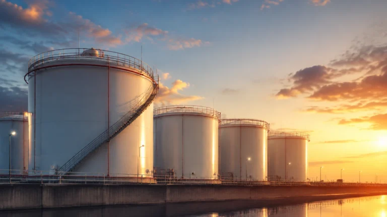
In industrial automation and process management, the selection of a level sensor for fuel tank applications is a critical decision that impacts operational efficiency, safety, and inventory accuracy. Fuel storage—whether it involves diesel for backup generators, aviation fuel, or heavy fuel oil for maritime vessels—presents unique challenges including volatile vapors, varying dielectric constants, and stringent explosion-proof requirements.
Reliable level measurement ensures that facilities avoid the risks of overfilling, which can lead to environmental contamination, or dry-running pumps, which causes mechanical damage and downtime. This guide examines the primary measurement principles used in fuel level monitoring, provides selection criteria, and outlines installation best practices for engineering professionals.
Measurement Principles for Fuel Level Monitoring
Understanding the physics behind different sensing technologies is the first step in selecting the appropriate level sensor for fuel tank environments. Each technology interacts with the fuel and the tank atmosphere differently.
1. Radar Level Measurement (Non-Contact and Guided)
Radar technology is widely considered the gold standard for fuel measurement. It operates on the Time-of-Flight (ToF) principle, where microwave pulses are emitted toward the fuel surface and reflected back to the sensor.
* Non-Contact Radar: These sensors emit high-frequency signals (typically 26GHz or 80GHz) through the air. They are ideal for fuel because they do not touch the media, reducing maintenance. 80GHz radar is particularly effective for fuel tanks because its narrow beam angle can avoid internal obstructions like heating coils or ladders.
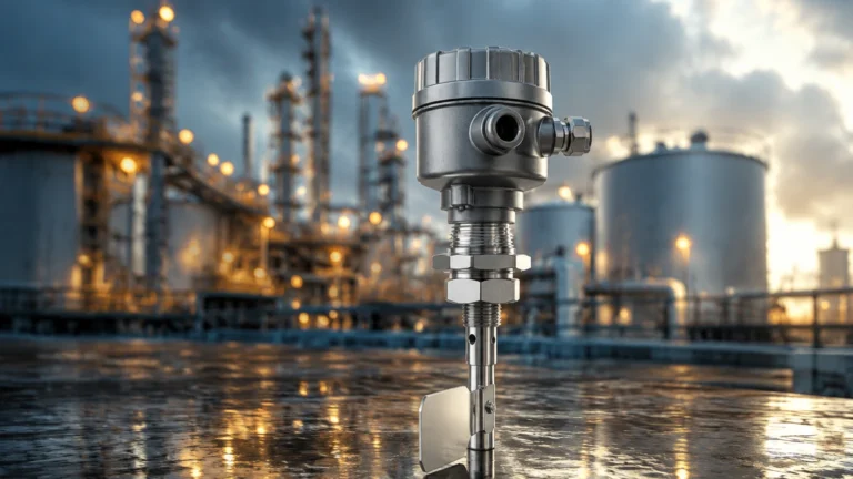
* Guided Wave Radar (GWR): A probe or cable guides the microwave pulse directly to the fuel. This is highly effective for fuels with low dielectric constants, as the probe concentrates the energy, ensuring a strong return signal even in turbulent conditions.
2. Ultrasonic Level Sensors
Ultrasonic sensors emit high-frequency sound waves. The time taken for the echo to return from the fuel surface determines the distance. While cost-effective, they are generally less suitable for high-volatility fuels (like gasoline) because the vapors can change the speed of sound in the tank headspace, leading to inaccuracies unless temperature compensation is perfectly calibrated.
3. Hydrostatic Pressure Transmitters
This method measures the pressure exerted by the liquid column at the bottom of the tank. Since pressure is directly proportional to the height of the liquid ($P = \rho gh$), the sensor can calculate the level if the density ($\rho$) of the fuel is known. These are robust and simple to install but require the fuel density to remain relatively constant.
4. Magnetic Level Gauges and Switches
For high-visibility local indication, magnetic level gauges use a float containing a magnet that moves with the fuel level inside a bypass chamber. This magnet flips colored flaps on a scale outside the chamber. For electronic output, a reed chain or magnetostrictive transmitter is often paired with the gauge to provide a 4-20mA signal to a control system.
Selecting the Right Level Sensor for Fuel Tank Applications
Choosing the correct instrument requires an analysis of the fuel type, tank geometry, and environmental conditions. The following factors should be confirmed before procurement.
Media Characteristics
Different fuels have different dielectric constants (εr). For example, diesel typically has a dielectric constant between 2.0 and 2.2. Low dielectric materials reflect less radar energy, which may necessitate the use of Guided Wave Radar or high-sensitivity non-contact radar. Additionally, if the fuel is heated (like heavy fuel oil), the sensor must be rated for the specific temperature range.
Tank Geometry and Constraints
* Horizontal vs. Vertical: Horizontal cylindrical tanks require linearization tables to convert level (mm) into volume (liters), a feature built into many modern transmitters.
* Underground Tanks: These often require sensors with high ingress protection (IP68) and long cable runs for hydrostatic or submersible options.
* Internal Obstructions: If a tank has agitators or internal bracing, a narrow-beam 80GHz radar or a guided wave radar is preferred to prevent false echoes.
Safety and Certification
Fuel is inherently flammable. Any level sensor for fuel tank use must typically carry hazardous area certifications such as ATEX, IECEx, or UL/CSA. This ensures the device is intrinsically safe or explosion-proof, preventing the instrument from becoming an ignition source.
Comparison of Fuel Level Sensing Technologies
| Technology | Accuracy | Ideal Fuel Type | Advantages | Limitations |
| :— | :— | :— | :— | :— |
| 80GHz Radar | ±1 mm | Diesel, Gasoline, HFO | Non-contact, ignores vapors, high precision | Higher initial cost |
| Guided Wave Radar | ±2 mm | Low-dielectric fuels | Reliable in turbulence/foam | Contact with media, probe length limits |
| Hydrostatic | ±0.1% to 0.5% | Heavy oils, Diesel | Simple, low cost, easy to retrofit | Sensitive to density changes |
| Ultrasonic | ±0.25% | Water-based or non-volatile fuel | Low cost, non-contact | Affected by heavy vapors and wind |
| Magnetostrictive | ±0.01% | High-precision diesel storage | Extremely accurate | Mechanical float can stick if fuel is dirty |
Installation Considerations and Best Practices
Proper installation is as important as selecting the right technology. Poor placement can lead to signal loss or erratic readings.
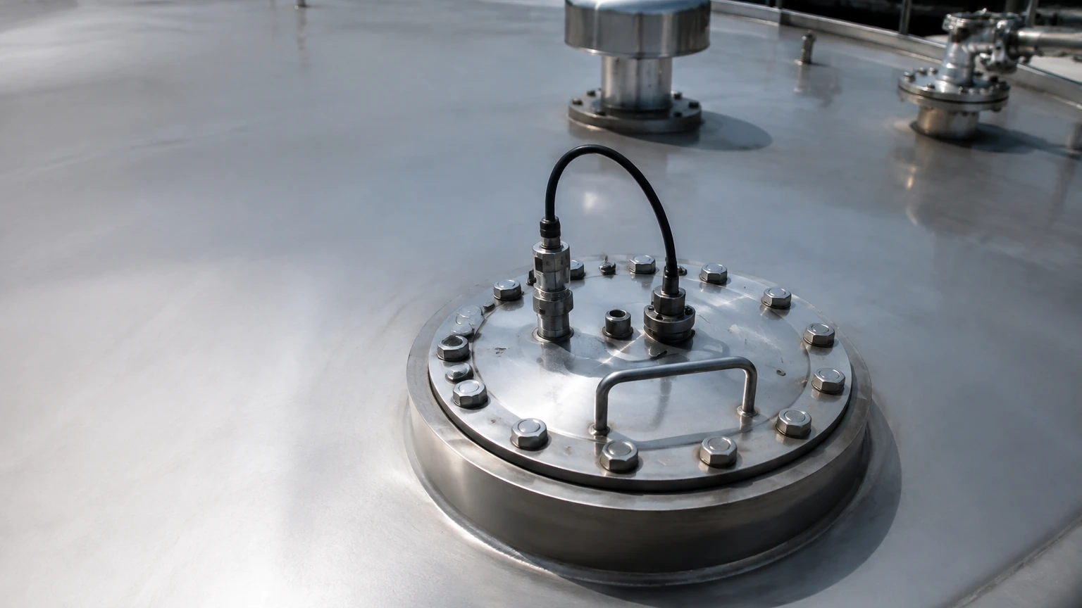
1. Nozzle Height and Diameter: For non-contact radar, the nozzle should be as short as possible. If the nozzle is too long or narrow, it can create internal reflections that interfere with the signal near the top of the tank (the "dead zone").
2. Avoid the Filling Stream: Never install a level sensor directly in the path of the incoming fuel. The turbulence and the physical liquid stream will cause signal noise and potential damage to the sensor probe.
3. Stilling Wells: In tanks with heavy turbulence or surface foam, installing the sensor (radar or ultrasonic) inside a stilling well (a vertical pipe) can provide a calm surface for measurement.
4. Grounding and Shielding: To prevent electromagnetic interference (EMI) from pumps or motors, ensure the sensor cable is shielded and the instrument is properly grounded according to the manufacturer’s specifications.
5. Venting: For hydrostatic sensors, the reference capillary in the cable must be kept clear and dry to ensure the sensor can compensate for changes in atmospheric pressure.
Limitations and Environmental Challenges
While modern sensors are highly advanced, certain conditions can challenge their performance:
* Vapor and Condensation: In gasoline tanks, high vapor concentrations can attenuate ultrasonic signals. Radar is generally immune to this, but heavy condensation on the sensor face can still cause a "blind" spot. Some radar sensors feature a PTFE drip-off lens to mitigate this.
* Paraffin Wax Buildup: In cold climates, diesel and heavy oils can develop paraffin wax buildup. This can coat the probes of guided wave radars or the floats of magnetic gauges, leading to mechanical failure or signal degradation.
* Tank Breathing: As tanks are filled and emptied, they "breathe." This moves air and moisture in and out, which can lead to corrosion of sensor housings if they are not made of high-grade stainless steel (e.g., 316L).
Frequently Asked Questions (FAQs)
Q: Can I use the same sensor for diesel and gasoline?
A: While many sensors are compatible with both, gasoline requires stricter explosion-proof ratings and handles differently due to its higher volatility. Always check the chemical compatibility of the sensor’s wetted parts (seals and probes) with the specific fuel.
Q: What is the "Dead Zone" in level measurement?
A: The dead zone, or blocking distance, is the area directly below the sensor where it cannot accurately measure. For example, if a radar has a 50mm dead zone, the tank cannot be measured accurately if the fuel level rises within 50mm of the sensor face.
Q: How often should a fuel level sensor be calibrated?
A: For inventory and fiscal billing, annual calibration is recommended. For general process monitoring, a functional check every 12 to 24 months is usually sufficient, depending on the stability of the technology used.
Q: Is non-contact radar better than hydrostatic pressure for fuel?
A: Radar is generally more accurate and requires less maintenance because it has no contact with the liquid. However, hydrostatic sensors are often more economical for deep, vented underground tanks where mounting a radar at the top is impractical.
Conclusion
Selecting a level sensor for fuel tank applications requires a balance between accuracy requirements, budget, and the physical properties of the fuel. For most modern industrial applications, radar technology offers the most robust solution, while hydrostatic and magnetic systems provide reliable alternatives for specific installation types. To explore a comprehensive range of industrial measurement instruments and technical specifications, professionals should Review product options and application support on the Main Page to ensure their selection aligns with global engineering standards.
By following the principles of measurement and adhering to strict installation guidelines, operators can ensure long-term reliability and safety in their fuel storage infrastructure.