Fuel Tank Level Equipment
Fuel Tank Level Equipment
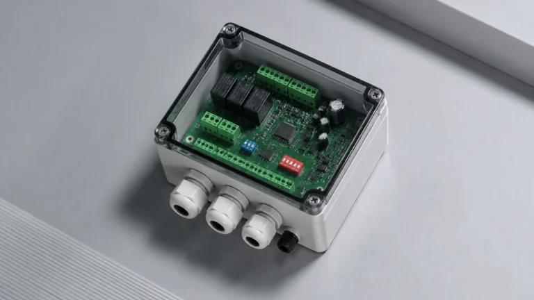
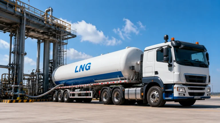
In industrial automation and process control, the precise monitoring of combustible liquids requires specialized fuel tank level equipment. Whether managing bulk storage for diesel generators, chemical feedstocks, or aviation fuel, the selection of a measurement technology impacts both operational efficiency and site safety. Modern instrumentation must account for the unique physical properties of hydrocarbons, including volatility, density fluctuations, and the potential for explosive atmospheres.
Selecting the correct fuel tank level equipment involves understanding the physics of the measurement principle and matching it to the specific constraints of the storage vessel and the medium itself. This guide examines the primary technologies used in the industry, providing a technical framework for engineers and procurement specialists.
Measurement Principles for Fuel Level Sensing
Before selecting a specific device, it is essential to understand the underlying physical principles that govern level detection in fuel applications. The most common methods include hydrostatic pressure, time-of-flight (radar and ultrasonic), and mechanical displacement.
Hydrostatic Pressure Measurement
Hydrostatic level transmitters measure the pressure exerted by the liquid column at the bottom of the tank. The relationship is defined by the formula $P = \rho \times g \times h$, where $P$ is pressure, $\rho$ is the density of the fuel, $g$ is gravity, and $h$ is the height of the liquid.
Because fuels like diesel or kerosene have specific gravities lower than water (typically 0.80 to 0.85), the transmitter must be calibrated to the specific density of the fluid. Hydrostatic sensors are frequently used in vented tanks where atmospheric pressure is constant. In pressurized tanks, a differential pressure (DP) approach is required to subtract the top-side vapor pressure from the total pressure at the bottom.
Radar (Radio Detection and Ranging)
Radar sensors utilize high-frequency electromagnetic waves, typically in the 26 GHz or 80 GHz range. There are two primary types used in fuel tank level equipment:
1. Non-Contact Radar: The sensor emits a signal that reflects off the fuel surface. The time-of-flight determines the distance. This is ideal for volatile fuels because the signal is unaffected by vapors or temperature gradients in the ullage space.
2. Guided Wave Radar (GWR): A probe or cable guides the microwave pulse directly to the liquid surface. GWR is highly effective for fuels with low dielectric constants, as the probe concentrates the energy, ensuring a strong return signal even from poorly reflective surfaces.
Ultrasonic Measurement
Ultrasonic sensors emit high-frequency sound pulses. While cost-effective for water-based liquids, they face challenges in fuel applications. The speed of sound is affected by the composition of the air/vapor mixture above the fuel. In tanks containing high-volatility fuels like gasoline, the heavy vapor concentration can attenuate the sound signal or alter the travel time, leading to inaccuracies unless temperature and vapor compensation are used.
Magnetic Level Gauges and Switches
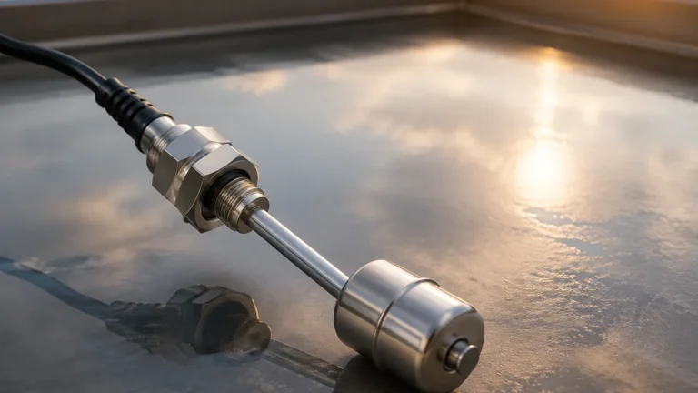
Magnetic level gauges utilize a float containing an internal magnet assembly that moves with the fuel level inside a bypass chamber. Outside the chamber, magnetic flags or a follower indicate the level visually. These are "dead-beat" mechanical systems that do not require power for visual indication, making them excellent for secondary safety monitoring. They can be equipped with reed switches or transmitters for remote signal output.
Key Evaluation Criteria for Fuel Applications
When evaluating fuel tank level equipment, engineers must look beyond basic height measurement. The following factors are critical for long-term reliability:
* Chemical Compatibility: Fuel components, especially additives in modern bio-diesels, can be corrosive. Wetted parts should typically be constructed from 316L stainless steel, PTFE, or specialized fluoroelastomers (FKM/Viton).
* Hazardous Area Ratings: Since most fuels are flammable, equipment must carry appropriate certifications such as ATEX, IECEx, or UL Class I, Div 1. This ensures the device is intrinsically safe or explosion-proof.
* Accuracy Requirements: For inventory management and custody transfer, high-precision instruments like 80 GHz radar or magnetostrictive probes are preferred. For simple pump control or high-level alarms, float switches or hydrostatic sensors may suffice.
* Tank Geometry: Tall, narrow silos may require guided wave radar to avoid interference from internal structures, while wide horizontal tanks are well-suited for non-contact radar or hydrostatic transmitters.
For a comprehensive overview of available technologies and technical specifications, engineers can refer to the Main Page of professional instrumentation providers.
Technical Comparison Table
| Technology | Accuracy | Ideal Media | Max Range | Notable Limitation |
| :— | :— | :— | :— | :— |
| Non-Contact Radar | ±1 mm to ±5 mm | Diesel, Jet Fuel, Crude | Up to 30m+ | Higher initial cost |
| Guided Wave Radar | ±2 mm | Low dielectric fuels | Up to 20m | Contact with media; probe fouling |
| Hydrostatic | ±0.1% to 0.5% FS | Heavy oils, Diesel | 0.5m to 20m | Sensitive to density changes |
| Ultrasonic | ±0.25% FS | Non-volatile fuels | 0.25m to 15m | Affected by vapor and foam |
| Magnetic Gauge | ±5 mm | Most hydrocarbons | Up to 6m | Requires side-mounting bypass |
Installation Considerations and Best Practices
Proper installation is as critical as selecting the right technology. Even the most advanced fuel tank level equipment will fail if the physical mounting environment is poorly planned.
1. The "Dead Zone" or Blocking Distance
All top-mounted sensors (Radar and Ultrasonic) have a "dead zone" immediately below the sensor face where measurement is impossible. When designing a tank, ensure the maximum fill level does not enter this zone. If the tank must be filled to the very top, a nozzle extension or a different technology (like a magnetic gauge) should be considered.
2. Nozzle Interference
For non-contact radar, the mounting nozzle's diameter and height can create false reflections. The internal surface of the nozzle should be smooth, and the sensor should be positioned so the signal beam does not hit the nozzle edge or internal tank obstructions like ladders, heating coils, or agitators.
3. Turbulence and Stilling Wells
In tanks with high-speed filling or agitation, the fuel surface can become turbulent. This scatters the signal of non-contact sensors. Installing a stilling well (a perforated pipe that acts as a localized calm zone) can stabilize the measurement. Guided wave radar is naturally more resistant to turbulence because the signal is confined to the probe.
4. Grounding and Lightning Protection
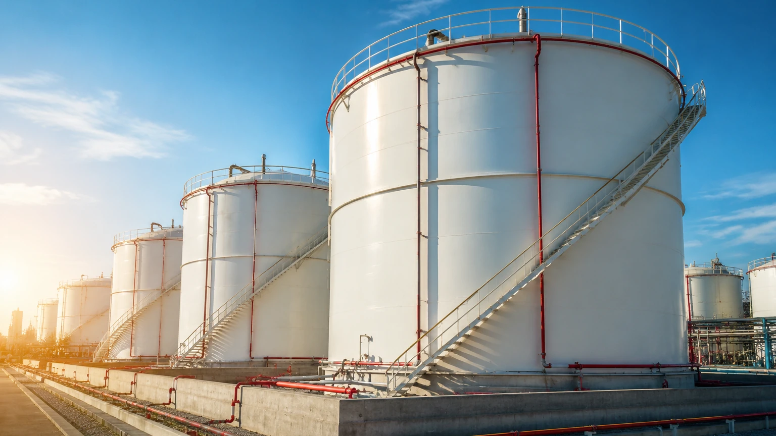
Fuel tanks are often located outdoors in exposed areas. Level transmitters should be properly grounded to prevent static buildup and protected with surge arrestors to mitigate damage from lightning strikes, which are a significant risk for electronic instrumentation in oil and gas environments.
Common Risks and Limitations
While modern fuel tank level equipment is robust, certain environmental factors can introduce errors:
* Density Variations: Hydrostatic sensors assume a constant density. If a tank is switched from Diesel (approx. 840 kg/m³) to a lighter fuel without recalibrating the transmitter, the level reading will be incorrect.
* Vapor and Condensation: In heavy fuel oil tanks that are heated, steam or heavy vapors can condense on sensor faces. Radar is generally immune to this, but ultrasonic sensors may lose signal. Some radar units feature a "drip-off" antenna design to prevent moisture buildup.
* Foaming: During rapid filling, some fuels can foam. Foam absorbs ultrasonic and radar signals, potentially causing a "lost echo" error. Guided wave radar is usually the best solution for foaming liquids as it can often detect the true liquid level through the foam.
Frequently Asked Questions (FAQ)
Q: Can I use the same sensor for diesel and gasoline?
A: Technically yes, provided the materials are compatible (e.g., 316 SS and Viton) and the electronics are rated for hazardous areas (Ex-proof). However, gasoline has a lower dielectric constant and higher vapor pressure, which may require a radar sensor rather than an ultrasonic one.
Q: How often should fuel level sensors be calibrated?
A: For inventory and fiscal applications, annual calibration is standard. For process control, a check every 24 months is usually sufficient, provided the fuel density remains consistent.
Q: Is it better to measure from the top or the bottom of the tank?
A: Top-down measurement (Radar/Ultrasonic) is generally preferred for maintenance because the sensor can be serviced without emptying the tank. Bottom-up measurement (Hydrostatic) is often more cost-effective for smaller, vented tanks.
Q: What is the impact of temperature on fuel level measurement?
A: Fuel expands as temperature rises. A volumetric measurement (level) will change even if the mass of the fuel remains the same. High-end systems include temperature compensation to provide "standardized volume" at 15°C (60°F).
Conclusion and Next Steps
Implementing reliable fuel tank level equipment requires a balance between precision, safety compliance, and budget. For most industrial fuel applications, radar technology (either non-contact or guided wave) provides the highest reliability due to its immunity to vapor and pressure changes. However, hydrostatic transmitters remain a viable, cost-effective solution for stable, vented storage.
Before finalizing a specification, engineers should confirm the tank dimensions, the specific gravity of the fuel at operating temperatures, and the required hazardous area certifications. For further technical support and to review specific product options, visit the Main Page to consult with application specialists.