Fuel Level Probe
Fuel Level Probe
In the landscape of industrial automation and resource management, the fuel level probe serves as a critical component for monitoring liquid assets. Whether managing diesel for backup generators, kerosene for aviation, or heavy fuel oil for maritime vessels, precise measurement is the difference between operational efficiency and costly downtime. This guide explores the engineering principles, selection criteria, and installation best practices for industrial fuel level probes.
Measurement Principles of Fuel Level Probes
Selecting the correct fuel level probe requires an understanding of the underlying physics used to detect the liquid-air interface. No single technology is universal; each has distinct advantages based on the fuel's chemical properties and the storage environment.
1. Capacitance-Based Measurement
Capacitance probes operate on the principle of an electrical capacitor. The probe acts as one electrode, and the tank wall (if metallic) or a secondary reference tube acts as the second electrode. The fuel serves as the dielectric material between them.
As the fuel level rises, it replaces the air (which has a dielectric constant of approximately 1) with fuel (which typically has a dielectric constant between 1.8 and 2.5). This change in the total dielectric constant of the medium results in a proportional change in capacitance. The electronics within the probe head convert this capacitance change into a standard 4-20mA or RS485 signal. This method is highly reliable for stationary tanks but requires recalibration if the fuel type (and thus the dielectric constant) changes significantly.
2. Magnetostrictive Technology
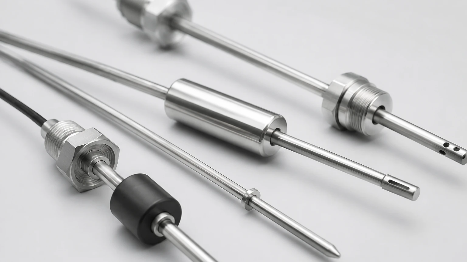
For high-precision applications, magnetostrictive probes are often the industry standard. These probes utilize a ferromagnetic waveguide inside a sensing tube. A float containing a permanent magnet moves along the tube as the fuel level changes.
The probe electronics send a current pulse down the waveguide, creating a magnetic field. When this field interacts with the magnetic field of the float, a torsional strain wave is generated (the Wiedemann effect). By measuring the time it takes for this wave to travel back to the sensor head, the system determines the float's position with sub-millimeter accuracy. This technology is ideal for custody transfer and leak detection.
3. Hydrostatic Pressure Sensing
Hydrostatic probes measure the pressure exerted by the liquid column above the sensor. The fundamental formula used is $P = \rho \cdot g \cdot h$, where $P$ is pressure, $\rho$ (rho) is the density of the fuel, $g$ is gravity, and $h$ is the height of the liquid.
These probes are typically submersible or mounted at the bottom of the tank. While cost-effective and easy to install, they are sensitive to changes in fuel density caused by temperature fluctuations. For accurate readings in outdoor environments, temperature compensation is mandatory.
4. Ultrasonic and Radar (Non-Contact)
Non-contact probes use Time-of-Flight (ToF) principles. Ultrasonic sensors emit sound waves, while radar sensors emit electromagnetic waves. The sensor measures the time taken for the signal to bounce off the fuel surface and return. Radar is generally preferred for fuel because it is unaffected by vapors, foam, or temperature gradients in the ullage space, which can distort ultrasonic signals.
Technical Selection Criteria
When evaluating a fuel level probe for a specific project, engineers must consider the following technical parameters to ensure long-term reliability.
Media Compatibility and Density
Different fuels have varying densities and viscosities. Diesel fuel typically has a density of 820 to 860 kg/m³, while heavy fuel oil (HFO) can exceed 900 kg/m³. If using a hydrostatic probe, the sensor must be calibrated to the specific gravity of the fuel. Furthermore, the probe materials (typically 316L stainless steel, PTFE, or Viton) must be chemically resistant to the fuel and any additives present.
Tank Geometry and Pressure
The physical dimensions of the tank dictate the probe length. For deep underground storage tanks (USTs), flexible magnetostrictive probes may be required to facilitate installation. For pressurized day tanks, the probe must be rated for the maximum operating pressure of the vessel.
Hazardous Area Certifications
Fuel storage environments are often classified as hazardous zones. Probes must carry appropriate certifications such as ATEX, IECEx, or UL/CSA for Class I, Division 1 or 2 areas. This ensures the device is intrinsically safe or explosion-proof, preventing the risk of ignition in the presence of flammable vapors.
Practical Selection Table
| Technology | Typical Accuracy | Max Range | Key Advantage | Primary Limitation |
| :— | :— | :— | :— | :— |
| Capacitance | ±1% FS | Up to 3m | No moving parts; low cost | Sensitive to dielectric shifts |
| Magnetostrictive | ±0.1mm | Up to 20m | Extremely high precision | Higher initial investment |
| Hydrostatic | ±0.5% FS | Up to 100m | Easy installation in deep tanks | Density dependent |
| Radar (80GHz) | ±2mm | Up to 30m | Non-contact; ignores vapors | Higher cost; mounting sensitive |
Installation Considerations
Proper installation is as critical as selecting the right technology. Failure to follow engineering guidelines often leads to signal noise or premature sensor failure.
1. Avoid Turbulence: Probes should not be installed directly near fuel inlet pipes. The turbulence from filling can cause mechanical stress on the probe or cause floats to bounce, leading to erratic readings. If the inlet cannot be moved, a stilling well (a perforated pipe) should be used to protect the probe.
2. Vertical Alignment: For float-based or capacitance probes, the device must be installed perfectly vertical. A tilt of even a few degrees can cause the float to bind against the sensing tube or change the effective capacitance path.
3. Dead Zones: Every fuel level probe has a "dead zone" at the top and bottom where measurement is not possible. For example, a hydrostatic probe cannot measure fuel below its sensing diaphragm. Engineers must account for these offsets in the control system logic.
4. Grounding and Shielding: To prevent EMI (Electromagnetic Interference) from pumps or motors, use shielded cables and ensure the probe head is properly grounded to the tank or a dedicated earth ground.
Limitations and Common Risks
While modern fuel level probes are highly advanced, they are not immune to environmental challenges. One of the primary risks in fuel management is water contamination. Water is denser than fuel and will settle at the bottom of the tank.
* Capacitance probes may read a sudden spike if water touches the electrodes, as water has a much higher dielectric constant (~80) than fuel (~2).
* Hydrostatic probes will report an incorrect level because the average density of the liquid column has changed.
* Magnetostrictive probes often solve this by using a dual-float system: one float calibrated to the density of the fuel and a second float calibrated to the density of water, allowing for simultaneous measurement of the fuel level and the water interface.
Another risk is paraffin precipitation in diesel fuel during cold weather. Wax crystals can build up on the probe surface or impede the movement of floats. In cold climates, heated probes or tank insulation may be necessary.
Frequently Asked Questions (FAQ)
Q: How often should a fuel level probe be calibrated?
A: For inventory management, an annual calibration check is recommended. For custody transfer or environmental compliance (leak detection), semi-annual calibration may be required by local regulations.
Q: Can one probe be used for different types of fuel?
A: It depends on the technology. Radar and magnetostrictive probes are generally versatile. Capacitance and hydrostatic probes require recalibration if switching between fuels with different dielectric constants or densities (e.g., switching from diesel to biodiesel).
Q: What is the maximum length for a rigid fuel probe?
A: Rigid probes are typically limited to 6 meters (20 feet) due to shipping and handling constraints. For tanks deeper than this, flexible probes are used.
Professional Level Measurement Solutions
Selecting the right instrumentation requires balancing technical requirements with budget constraints. Welk provides a comprehensive range of industrial measurement tools designed for the rigors of fuel and oil management. From high-precision magnetostrictive sensors to robust hydrostatic transmitters, our solutions ensure accurate inventory tracking and operational safety.
For detailed specifications on our full range of level measurement instruments, including radar, ultrasonic, and magnetic gauges, please visit our Main Page to review product options and application support. Our engineering team is available to assist with custom OEM/ODM requirements and site-specific selection advice.
Summary of Best Practices
* Confirm Fuel Specifications: Always know the dielectric constant and density of the fuel before selecting a probe.
* Check Certifications: Ensure the probe meets the specific hazardous area requirements of your facility.
* Account for Temperature: Use temperature-compensated probes for outdoor tanks to prevent volume errors caused by thermal expansion.
* Plan for Maintenance: Install probes in locations that allow for easy removal for cleaning and inspection without draining the tank.