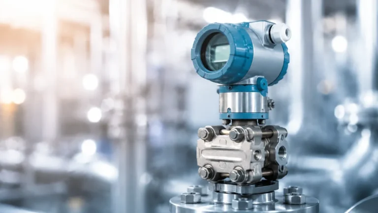
Level Controls
Level Controls
In industrial automation and process engineering, level controls are the fundamental components used to monitor and manage the volume of liquids, solids, or slurries within a vessel. Whether the application involves a small chemical dosing tank or a massive municipal water reservoir, the selection of the correct level control technology directly impacts operational safety, inventory accuracy, and system efficiency. This guide examines the core principles of level measurement, compares various technologies, and provides practical engineering considerations for successful implementation.
Understanding the Principles of Level Measurement
Before selecting a specific device, it is essential to understand the physical principles that govern how level controls detect the interface between air and the process medium. Modern industrial instruments generally fall into two categories: non-contact and contact-based measurement.
Radar Level Measurement (Time-of-Flight)
Radar level meters utilize high-frequency electromagnetic waves, typically in the 26 GHz or 80 GHz range. The sensor emits a pulse toward the material surface, which reflects a portion of that energy back to the receiver. By measuring the time-of-flight (the duration it takes for the signal to travel to the surface and back), the instrument calculates the distance. Because electromagnetic waves travel at the speed of light and are largely unaffected by air temperature, pressure, or vacuum, radar is considered one of the most versatile and accurate methods for level control.
Ultrasonic Level Measurement (Acoustic)
Similar to radar, ultrasonic sensors use the time-of-flight principle but rely on sound waves rather than electromagnetic pulses. A transducer emits an ultrasonic pulse (typically between 20 kHz and 200 kHz) that reflects off the surface of the medium. While cost-effective and reliable for many water treatment applications, ultrasonic waves are mechanical and require a medium (air) to travel. Consequently, they are sensitive to changes in air temperature, heavy foam, and high-pressure environments which can alter the speed of sound.
Hydrostatic Level Measurement (Pressure-Based)
Hydrostatic level transmitters operate on the principle that the pressure at the bottom of a liquid column is directly proportional to the height of the liquid and its density. The formula $P = \rho \cdot g \cdot h$ (where $P$ is pressure, $\rho$ is density, $g$ is gravity, and $h$ is height) allows the sensor to determine the level by measuring the weight of the liquid above it. This method is highly effective for vented tanks but requires compensation if the tank is pressurized or if the liquid density changes significantly with temperature.
Magnetic and Buoyancy Principles
Magnetic level gauges and float switches utilize buoyancy. A float containing a permanent magnet moves with the liquid level. In a magnetic gauge, this float interacts with external flags or a sensing rod to provide visual or electronic feedback. This is a robust, mechanical approach that provides a clear physical indication of the level without requiring power for the visual component.
Point Level vs. Continuous Level Controls
Level controls are further categorized by the type of feedback they provide to the control system. Choosing between point level and continuous level measurement depends on whether the goal is simple automation or granular process monitoring.
Point Level Controls
Point level controls, often referred to as level switches, detect the presence or absence of material at a specific height. They are typically used for:
- High-level alarms: Preventing tank overflows.
- Low-level alarms: Protecting pumps from running dry.
- Pump control: Turning a pump on at one level and off at another (hysteresis).
Common technologies for point level include tuning forks (vibrating probes), capacitive switches, and float switches. These are binary devices (on/off) and are generally simpler to install and maintain.
Continuous Level Controls
Continuous level controls provide a real-time, analog, or digital signal (such as 4-20mA, HART, or Modbus) representing the exact level across the entire measurement range. This is necessary for:
- Inventory management: Knowing exactly how much raw material is in stock.
- Process optimization: Maintaining a specific level for chemical reactions or heat exchange.
- Trend analysis: Monitoring usage rates over time.
Radar, ultrasonic, and hydrostatic transmitters are the primary choices for continuous level measurement. For a comprehensive look at the hardware available for these applications, engineers can visit the Main Page of professional manufacturers to review specific technical data sheets.
Selection Criteria for Industrial Level Controls
Selecting the right instrument requires a detailed analysis of the process conditions. The following table summarizes the primary considerations for the most common technologies.
| Technology | Typical Accuracy | Max Range | Best For | Main Limitations |
| :— | :— | :— | :— | :— |
| 80 GHz Radar | ±1 mm | 120 m | Corrosive chemicals, solids, precision tanks | High initial cost compared to ultrasonic |
| Ultrasonic | ±0.25% of range | 15–30 m | Water, wastewater, open channels | Affected by foam, dust, and vacuum |
| Hydrostatic | ±0.1% to 0.5% | 200 m (H2O) | Deep wells, vented tanks, oils | Sensitive to density changes |
| Magnetic Gauge| ±5 mm to 10 mm | 6 m | High pressure/temp, visual monitoring | Mechanical wear; requires clean liquids |
| Capacitance | ±1% | 30 m | Conductive/non-conductive liquids | Requires calibration; coating buildup issues |
Key Evaluation Factors
1. Media Characteristics: Is the material a liquid, solid, or slurry? Is it corrosive, viscous, or prone to coating the sensor? For example, radar is preferred for corrosive acids because the sensor can be completely sealed in PTFE.
2. Process Temperature and Pressure: Ultrasonic sensors are limited to relatively low pressures (typically < 3 bar), whereas radar and magnetic gauges can handle extreme pressures exceeding 100 bar and temperatures over 400°C.
3. Tank Geometry: Internal obstructions like agitators, heating coils, or ladders can interfere with radar and ultrasonic signals. In these cases, a guided wave radar or a stilling well may be required.
4. Accuracy Requirements: If the goal is custody transfer or high-value chemical dosing, a high-frequency radar with ±1 mm accuracy is necessary. For simple sump pump control, a hydrostatic sensor or ultrasonic unit is sufficient.
Installation Best Practices for Reliable Performance
Even the most advanced level controls will fail if installed incorrectly. Proper placement and mounting are critical to ensuring the longevity and accuracy of the instrument.
Dead Zones (Blocking Distance)
Every non-contact sensor (radar and ultrasonic) has a "dead zone" or "blocking distance" directly beneath the sensor face. In this zone, the instrument cannot accurately process the return signal. Engineers must ensure that the maximum possible liquid level never enters this dead zone. If the tank is frequently filled to the top, a nozzle extension or a taller mounting bracket may be required.
Nozzle Design and Placement
For radar and ultrasonic units, the sensor should be mounted away from the tank wall to avoid false reflections. A general rule of thumb is to place the sensor at least 200 mm or 1/6th of the tank diameter away from the wall. Additionally, the sensor should not be mounted directly above the fill inlet, as the falling stream of material will interfere with the signal.
Stilling Wells and Bypass Chambers
In applications with heavy turbulence, foam, or internal obstructions, a stilling well (a vertical pipe inside the tank) or a bypass chamber (a pipe mounted outside the tank) can be used. These accessories provide a calm surface for the sensor to measure, effectively isolating the measurement from process disturbances. This is particularly common when using magnetic level gauges or guided wave radar.
Grounding and Shielding
Industrial environments are often filled with electromagnetic interference (EMI) from large motors and variable frequency drives (VFDs). Level controls should be wired using shielded cables, and the instrument housing must be properly grounded to the vessel or the plant's common ground to prevent signal noise and erratic readings.

Operational Limitations and Environmental Challenges
No single technology is a "silver bullet" for every application. Understanding the limitations of level controls is essential for risk mitigation.
- Foam: Heavy, thick foam can absorb ultrasonic and radar signals, leading to a "loss of echo" error. In these scenarios, hydrostatic pressure sensors or guided wave radar (which uses a physical probe to guide the signal) are more reliable.
- Vapor and Condensation: While radar is mostly immune to vapors, heavy condensation on an ultrasonic transducer face can dampen the vibration, leading to measurement failure. Some sensors feature a "drip-off" design to mitigate this.
- Dust: In solid level measurement (e.g., grain or cement silos), dust clouds can attenuate signals. High-frequency 80 GHz radar is typically the best solution here due to its ability to penetrate dust and its narrow beam angle, which avoids silo walls.
- Density Fluctuations: Hydrostatic sensors assume a constant density. If a tank is used for different liquids or if the temperature swings wildly (causing the liquid to expand or contract), the level reading will drift unless a temperature-compensated system or a different technology is used.
Frequently Asked Questions (FAQs)
Q: How often do level controls need calibration?
A: This depends on the technology. Radar and ultrasonic units are generally "set and forget" once the tank geometry is programmed. Hydrostatic sensors may require annual zero-point checks to account for sensor drift. Capacitance probes require recalibration if the dielectric constant of the media changes.
Q: Can I use an ultrasonic sensor in a vacuum?
A: No. Ultrasonic waves require a medium (like air or nitrogen) to transmit sound. In a vacuum, there is no medium to carry the sound wave, so the sensor will not function. Radar is the preferred choice for vacuum applications.
Q: What is the difference between 2-wire and 4-wire level transmitters?
A: A 2-wire transmitter receives its power from the same 4-20mA loop used for the signal, making it easier and cheaper to wire. A 4-wire transmitter has separate pairs for power and signal, which is often necessary for power-intensive features like heated displays or high-power radar pulses.
Q: How do I handle measurement in tanks with agitators?
A: Agitator blades create both surface turbulence and physical obstructions. Software-based "false echo suppression" can be used to tell the sensor to ignore the blades. Alternatively, installing the sensor in a stilling well provides a stable environment for measurement.
Conclusion
Effective level control is a cornerstone of modern industrial processing. By understanding the underlying physics—whether it be the time-of-flight of a radar pulse or the hydrostatic pressure of a liquid column—engineers can select the most robust and cost-effective solution for their specific needs. Proper attention to installation details, such as nozzle placement and dead zones, ensures that these instruments provide accurate data for years of operation. For those seeking specific product specifications or customized OEM solutions, consulting the Main Page of an established manufacturer is the recommended next step in the procurement process.