Non Contact Level Measurement
Non Contact Level Measurement
In modern industrial automation, the ability to monitor liquid and solid levels without physical interaction with the media has become a standard requirement for safety, hygiene, and long-term reliability. Non contact level measurement refers to a suite of technologies—primarily radar and ultrasonic—that determine the distance to a product surface by emitting signals and measuring their return. This approach eliminates the risks of sensor corrosion, mechanical wear, and contamination, making it the preferred choice for aggressive chemicals, wastewater, and food-grade applications.
As a professional manufacturer of industrial level measurement instruments, Welk provides high-precision solutions designed to meet these challenges. Understanding the underlying physics of these technologies is the first step in selecting the correct instrument for a specific process environment. For a comprehensive overview of available technologies, engineers can refer to the Main Page for detailed product specifications.
Measurement Principles
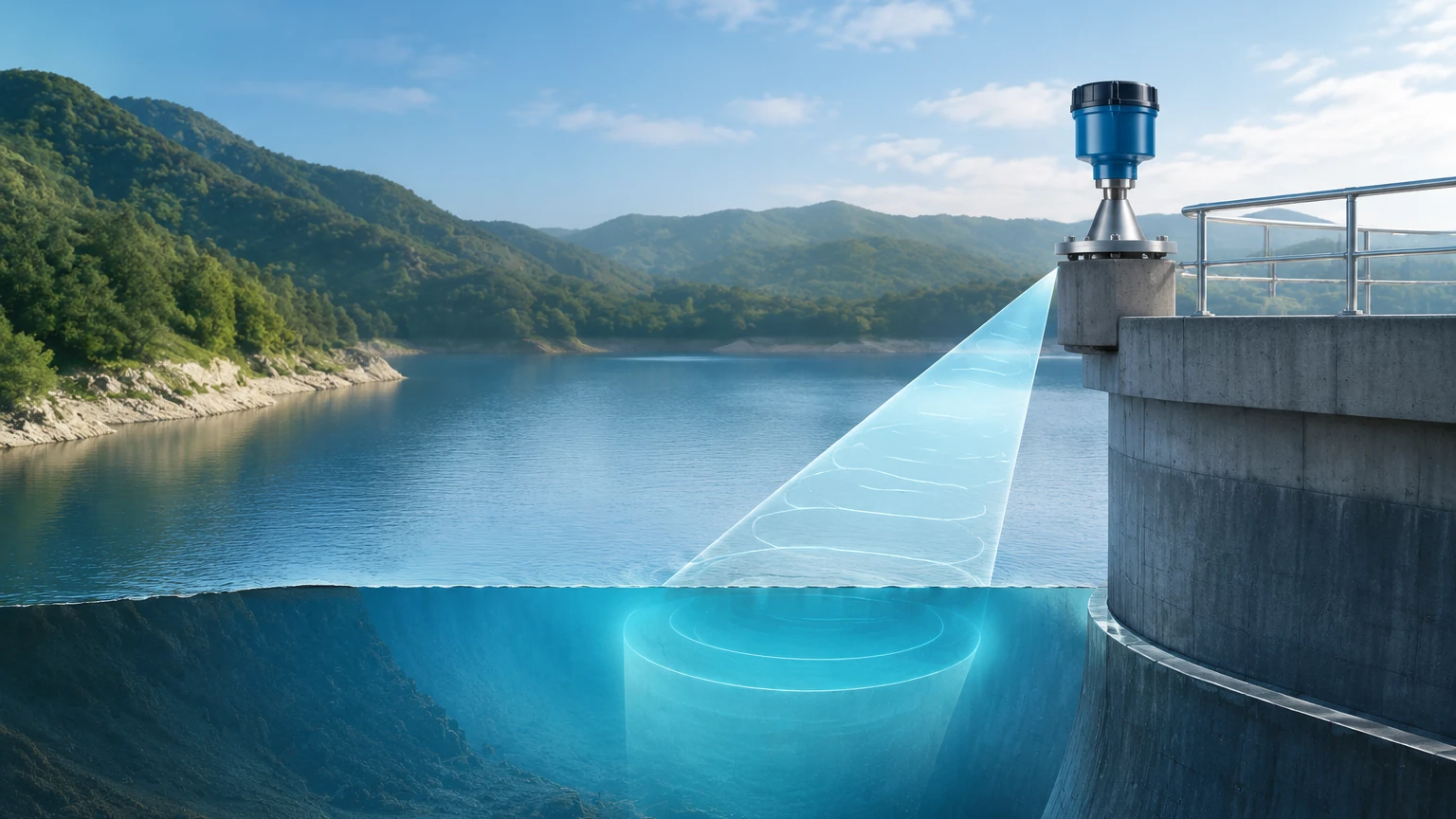
Non contact level measurement relies on the "Time of Flight" (ToF) principle. The sensor, mounted at the top of a vessel, emits a pulse toward the material below. This pulse reflects off the surface of the medium and returns to the sensor. By calculating the time elapsed between emission and reception, the device determines the distance.
Ultrasonic Level Measurement
Ultrasonic sensors utilize high-frequency sound waves (typically between 20 kHz and 200 kHz). The transducer acts as both a transmitter and a receiver.
* The Process: A pulse is sent, and the device waits for the echo. Since the speed of sound in air is approximately 343 meters per second (at 20°C), the distance is calculated as: *Distance = (Speed of Sound × Time) / 2*.
* Atmospheric Sensitivity: Because sound requires a medium (air or gas) to travel, the speed is influenced by air temperature, humidity, and pressure. Most industrial ultrasonic sensors include an integrated temperature sensor to compensate for these fluctuations automatically.
Radar Level Measurement
Radar (Radio Detection and Ranging) uses electromagnetic waves, typically in the microwave spectrum. Unlike sound, radar waves do not require a medium and travel at the speed of light.
* Pulse Radar: Similar to ultrasonic, it sends a discrete microwave pulse and measures the time delay.
* FMCW (Frequency Modulated Continuous Wave): Modern high-precision radar, such as 80GHz systems, uses FMCW. The sensor emits a continuous signal with a constantly changing frequency. The difference in frequency between the emitted and reflected signal is proportional to the distance. This allows for much higher accuracy (often ±1mm).
* Dielectric Constant (εr): The strength of the reflection depends on the dielectric constant of the material. Materials with high dielectric constants (like water) reflect signals strongly, while low-dielectric materials (like oil or plastic pellets) may require more sensitive electronics or specialized antennas.
Technology Selection Criteria
Choosing between ultrasonic and radar depends on the physical properties of the medium and the environmental conditions inside the tank. The following table provides a comparison for engineering selection.
| Feature | Ultrasonic Sensors | Radar Level Meters (80GHz) |
| :— | :— | :— |
| Medium Compatibility | Primarily liquids and simple solids | Liquids, solids, slurries, and powders |
| Accuracy | ±0.25% to ±0.5% of range | ±1mm to ±2mm |
| Measurement Range | 0.2m to 30m (0.6ft to 98ft) | 0.1m to 120m (0.3ft to 393ft) |
| Pressure Limits | Near-atmospheric (up to 0.3 MPa) | High pressure (up to 10 MPa/100 bar) |
| Temperature Limits | -40°C to +80°C | -40°C to +250°C (standard) |
| Effect of Dust/Vapor | Significant (blocks sound) | Minimal (penetrates dust/vapor) |
| Cost Profile | Economical | Higher initial investment |
Practical Installation Considerations
Even the most advanced non contact level measurement device will fail if installed incorrectly. Several physical factors must be accounted for during the design phase.
1. The Dead Zone (Blocking Distance)
Every non-contact sensor has a "Dead Zone" or "Blanking Distance" directly beneath the transducer face. This is the area where the sensor cannot process a return signal because the transducer is still vibrating from the emission.
* Ultrasonic: Typically 0.2m to 0.8m depending on the frequency.
* Radar: Much smaller, often 0.1m or less.
* Guideline: Ensure the maximum high-level of the liquid never enters this zone, or the sensor will provide an error or a false high-level reading.
2. Beam Angle and Obstructions
The signal spreads out in a cone shape. Any internal tank structures—such as ladders, agitators, heating coils, or inflow pipes—that fall within this cone will create "false echoes."
* Narrow Beams: 80GHz radar offers a very narrow beam angle (often 3° to 6°), allowing it to be installed in tall, narrow nozzles or tanks with internal obstructions.
* Ultrasonic Beams: Usually wider (around 10° to 12°), requiring a clear path to the surface.
3. Nozzle Positioning
* Avoid the Center: Do not install the sensor in the exact center of a circular tank. This can lead to multiple reflections (parabolic effect) that confuse the sensor.
* Avoid the Wall: Stay away from the tank wall to prevent signal interference from weld seams or build-up. A general rule is to maintain a distance from the wall equal to 1/6th of the tank diameter.
* Inflow: Never install the sensor directly above the filling stream, as the turbulence and the falling material will interrupt the signal.
Environmental Limitations
While non-contact methods are versatile, certain process conditions present significant challenges:
* Heavy Foam: Foam acts as an acoustic and electromagnetic absorber. Light, airy foam might allow a signal through, but thick, dense foam often absorbs the pulse entirely, resulting in a "Loss of Echo." In these cases, a stilling well or a contact-based technology like a magnetic level gauge may be required.
* Vacuum Conditions: Ultrasonic waves cannot travel in a vacuum. For vacuum tanks, radar is the only viable non-contact option.
* Extreme Turbulence: Rapidly moving surfaces scatter the signal. This can be mitigated through software filtering (damping) or by installing the sensor inside a bypass pipe or stilling well to provide a calm surface for measurement.
Application Engineering Examples
Water and Wastewater Treatment
Non contact level measurement is the industry standard for monitoring sewage sumps, wet wells, and open channel flow. Ultrasonic sensors are frequently used here due to their cost-effectiveness. Because these environments are often humid, the non-contact nature prevents the sensor from being fouled by grease and debris common in wastewater.
Chemical Processing
For corrosive acids like HCl or H2SO4, radar sensors with PTFE-faced antennas offer total chemical resistance. Since the sensor never touches the liquid, there is no risk of the instrument housing being compromised by the media. The ability of radar to ignore heavy vapors makes it superior to ultrasonic in closed chemical storage tanks.
Bulk Solids and Silos
Measuring the level of grain, cement, or plastic pellets involves dusty environments and uneven surfaces (slopes). High-frequency radar (80GHz) is particularly effective here because the electromagnetic waves penetrate dust clouds that would otherwise block ultrasonic sound waves. Furthermore, the narrow beam can be aimed at specific points on the material slope to get a representative average level.
Maintenance and Troubleshooting
One of the primary benefits of non-contact systems is the low maintenance requirement. However, periodic checks are recommended:
* Transducer Cleaning: In high-humidity applications, condensation or crystallization can occur on the sensor face. While many modern radars can "see through" a thin film of moisture, heavy build-up will eventually degrade the signal.
* Signal-to-Noise Ratio: Most digital level meters provide a diagnostic value for signal strength. Monitoring this via a PLC can provide an early warning that the sensor needs cleaning or that the process conditions (like foam) are changing.
* False Echo Mapping: If a new obstruction is added to the tank (e.g., a new pipe), the sensor should be re-calibrated to "map out" the new static reflection so it is ignored during measurement.
Frequently Asked Questions (FAQ)
Q: Can I use an ultrasonic sensor on a tank under pressure?
A: Generally, no. Ultrasonic sensors are designed for atmospheric or near-atmospheric pressure. Changes in pressure significantly alter the speed of sound and can damage the transducer diaphragm. Radar is the appropriate choice for pressurized vessels.
Q: Does the color of the liquid affect the measurement?
A: No. Unlike optical or laser sensors, both radar and ultrasonic measurements are independent of the color or transparency of the medium.
Q: How do I measure level in a tank with a heavy agitator?
A: Use a radar sensor with a narrow beam angle and position it as far from the agitator blades as possible. Most Welk radar units include a "False Echo Suppression" feature that allows the software to memorize the reflections from the agitator and ignore them.
Q: What is the maximum distance for non-contact measurement?
A: For liquids, high-frequency radar can measure up to 120 meters (393 feet). Ultrasonic is typically limited to 30 meters (98 feet) due to the attenuation of sound waves in air.
For technical support in selecting the right instrument for your specific application, or to view our full range of radar and ultrasonic transmitters, please visit our Main Page. Welk provides customized OEM and ODM services to ensure that every industrial level measurement challenge is met with a reliable, accurate, and cost-effective solution.