Well Water Level Sensor
Well Water Level Sensor
Monitoring groundwater levels is a fundamental requirement for municipal water supply, agricultural irrigation, and industrial process management. A reliable well water level sensor provides the data necessary to prevent pump dry-running, manage aquifer sustainability, and ensure a consistent water supply. In deep well applications, the environment presents unique challenges, including narrow access pipes, high static pressure, and potential sediment buildup. Selecting the appropriate technology requires an understanding of the physical principles governing level measurement and the specific constraints of the borehole or well.
Measurement Principles for Well Water Monitoring
There are several primary methods used to measure water levels in wells, each relying on different physical properties. Before selecting a device, engineers must evaluate whether a contact or non-contact method is most suitable for the specific site conditions.
Hydrostatic Pressure Measurement
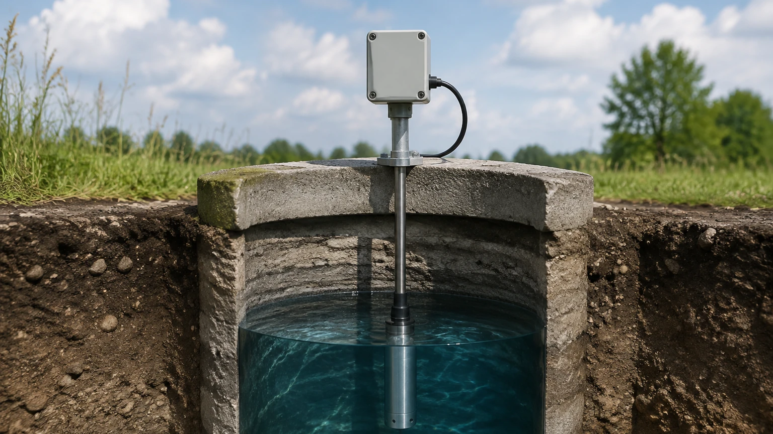
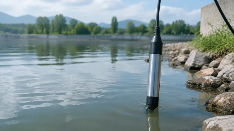
Hydrostatic level transmitters are the most common solution for deep wells. These sensors are submerged directly into the water. The principle is based on the relationship between the height of the liquid column and the pressure exerted at the base of the sensor. The formula used is $P = \rho \cdot g \cdot h$, where $P$ is pressure, $\rho$ is the density of the liquid, $g$ is gravity, and $h$ is the height of the liquid above the sensor.
To ensure accuracy, these sensors must account for atmospheric pressure changes. This is typically achieved through a vented cable that allows the internal side of the pressure diaphragm to remain at atmospheric pressure, effectively canceling out weather-related pressure fluctuations.
Ultrasonic (Non-Contact)
Ultrasonic sensors are mounted at the top of the well and emit high-frequency sound pulses. The sensor measures the time it takes for the pulse to travel to the water surface and return. While convenient because they do not touch the water, ultrasonic sensors are often limited by the narrow diameter of well casings. If the beam angle is too wide, the signal may reflect off the casing walls rather than the water surface, leading to false readings.
Radar (Non-Contact)
Radar level meters, particularly those operating at high frequencies like 80GHz, offer a more precise non-contact alternative. They use electromagnetic waves rather than sound. Because radar waves have a much narrower beam angle and are unaffected by air temperature or vapor, they are increasingly used in large-diameter wells or open-pit sumps where high precision is required. For more technical specifications on these technologies, engineers can consult the Main Page of industrial instrumentation providers.
Technology Selection Table
The following table compares the primary technologies used for well water level sensing to assist in the initial selection process.
| Feature | Hydrostatic Submersible | Ultrasonic (Non-Contact) | Radar (80GHz) |
| :— | :— | :— | :— |
| Typical Range | 0–500m (0–1640 ft) | 0–15m (0–49 ft) | 0–120m (0–393 ft) |
| Accuracy | ±0.1% to ±0.5% FS | ±0.25% FS | ±1mm to ±2mm |
| Installation | Submerged in well | Top-mounted | Top-mounted |
| Pros | Unaffected by foam/narrow pipes | No contact with liquid | High precision, narrow beam |
| Cons | Potential for silt buildup | Limited range, beam interference | Higher initial cost |
| Best Use Case | Deep boreholes, narrow wells | Shallow wells, tanks | High-accuracy industrial wells |
Key Evaluation Criteria for Well Water Level Sensors
When specifying a well water level sensor, several technical factors must be confirmed to ensure long-term reliability and data integrity.
1. Well Depth and Measurement Range
The total depth of the well determines the required cable length for hydrostatic sensors or the signal strength for radar/ultrasonic units. For deep boreholes exceeding 100 meters (328 ft), hydrostatic sensors are preferred due to their ability to provide stable readings regardless of the distance from the wellhead.
2. Casing Diameter
In many monitoring wells, the casing diameter may be as small as 25mm to 50mm (1 to 2 inches). This narrow space restricts the use of most non-contact sensors. Submersible hydrostatic sensors are designed with slim profiles, often as small as 16mm to 22mm in diameter, making them ideal for restricted spaces.
3. Water Quality and Material Compatibility
While most well water is relatively clean, some groundwater contains high levels of minerals, salinity, or corrosive elements. Standard sensors typically use 316L stainless steel. However, in brackish or highly corrosive environments, materials like Titanium or specialized coatings may be necessary to prevent pitting and sensor failure.
4. Signal Output and Integration
Modern industrial automation requires seamless data integration. Common outputs include 4-20mA analog signals for simple pump control or digital protocols like RS485 (Modbus RTU) for integration into SCADA systems and remote telemetry units (RTUs). For remote locations, low-power sensors are essential for battery or solar-powered data logging.
Installation Considerations and Best Practices
Proper installation is as critical as sensor selection. Even the highest quality well water level sensor will fail if the installation environment is not correctly prepared.
* Cable Support and Strain Relief: For deep wells, the weight of the cable itself can cause stretching or damage to the internal conductors. It is recommended to use a cable clamp or support grip at the wellhead to distribute the weight.
* Venting and Moisture Protection: Hydrostatic sensors with vented cables must be protected from moisture ingress. A desiccant cartridge or a specialized junction box should be used at the surface end of the vent tube to prevent condensation from blocking the tube or damaging the electronics.
* Positioning Relative to the Pump: The sensor should be installed at a depth where it remains submerged even during maximum drawdown, but it should be positioned away from the immediate turbulence of the pump intake. This prevents "noise" in the level data caused by the pump's operation.
* Still Wells: In wells with significant turbulence or falling water from side-entry pipes, installing the sensor inside a "still well" (a perforated PVC pipe) can help stabilize the readings.
Common Risks and Limitations
Engineers should be aware of the following risks when deploying level sensors in groundwater applications:
1. Lightning and Surges: Since wells are often located in open areas and the sensor cable acts as a long conductor, they are highly susceptible to lightning strikes. Integrated surge protection in the sensor and additional protection at the control panel are strongly recommended.
2. Silt and Sedimentation: In some wells, sediment can accumulate at the bottom, potentially burying a submersible sensor or clogging the pressure port. Regular maintenance or suspending the sensor slightly above the bottom can mitigate this risk.
3. Atmospheric Pressure Lag: In very deep wells with long vented cables, there can be a slight delay in atmospheric pressure compensation if the vent tube is restricted or too small in diameter. Ensuring the vent tube is clear is a standard maintenance task.
Frequently Asked Questions (FAQ)
Q: How often should a well water level sensor be calibrated?
A: For most industrial and municipal applications, an annual calibration check is recommended. This can be done by comparing the sensor reading against a manual electric contact water level meter (dip tape).
Q: Can I use a standard pressure transmitter instead of a submersible one?
A: A standard pressure transmitter mounted at the surface can only measure the pressure at the pump outlet, not the actual water level in the well. To measure the level (the height of the water table), a submersible sensor or a top-mounted non-contact sensor is required.
Q: What happens if the vented cable is submerged in water at the surface?
A: If the vent tube at the surface end of the cable is submerged or blocked by water, the sensor will no longer be able to compensate for atmospheric pressure changes, leading to significant measurement errors (approximately 10cm of error for every 10mbar of pressure change).
Q: Are there wireless options for well water level sensing?
A: Yes, many systems now integrate the sensor with a cellular or LoRaWAN gateway at the wellhead, allowing for remote monitoring without the need for long cable runs to a central control room.
Conclusion for Project Planning
Before proceeding with a procurement or installation project, the following information should be confirmed:
* The maximum expected depth of the water table (drawdown level).
* The internal diameter of the well casing.
* The chemical composition of the water (to determine material compatibility).
* The required data transmission distance and power availability at the site.
By carefully matching the sensor technology to the physical constraints of the well, operators can ensure accurate, long-term monitoring of their water resources. For a comprehensive review of available hardware and integration options, visiting the Main Page of an industrial manufacturer like Welk provides access to detailed data sheets and application support.