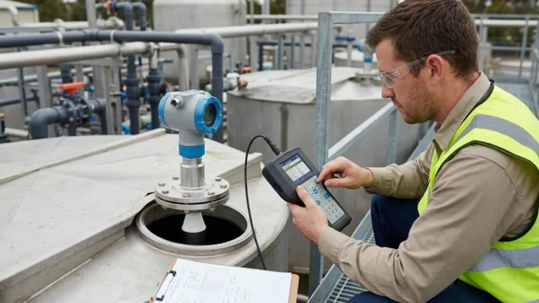
Ultrasonic Level Sensor and Transmitter
Ultrasonic Level Sensor and Transmitter: A Technical Guide for Industrial Applications
In the landscape of industrial process control, the ability to monitor liquid and solid levels without physical contact is a significant advantage. The ultrasonic level sensor and transmitter has become a cornerstone technology for engineers seeking reliable, low-maintenance, and cost-effective measurement solutions. From municipal water treatment to complex chemical processing, these instruments provide the data necessary for inventory management, pump control, and safety monitoring.
Welk specializes in high-precision industrial level measurement, offering a range of Ultrasonic Level Meters designed to withstand the rigors of modern automation. This guide explores the fundamental physics, selection criteria, and practical installation requirements for these essential devices.
Understanding the Measurement Principle
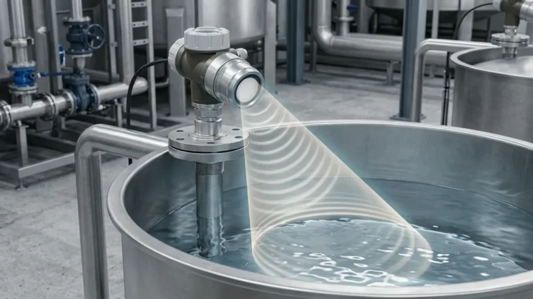
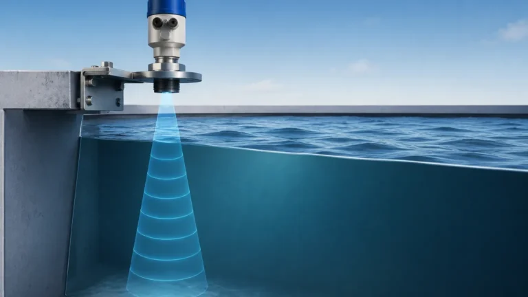
Ultrasonic level measurement is based on the "Time-of-Flight" (ToF) principle. The device consists of a transducer containing a piezoelectric crystal that serves both as a transmitter and a receiver.
The Physics of Sound Waves
1. Emission: The transmitter emits a short burst of ultrasonic energy (typically between 20 kHz and 200 kHz) toward the surface of the medium.
2. Reflection: When these sound waves hit the surface of the liquid or solid, they are reflected back toward the sensor as an echo.
3. Detection: The sensor detects the returning echo and the internal processor measures the exact time elapsed between emission and reception.
The Calculation
The distance from the sensor face to the material surface is calculated using the formula:
Distance = (Speed of Sound × Time Delay) / 2
Since the speed of sound in air is approximately 344 m/s (1,128 ft/s) at 20°C (68°F), the transmitter can determine the distance with high precision. By subtracting this distance from the known tank height (the "empty" calibration point), the device calculates the actual level of the material.
Temperature Compensation
The speed of sound is not constant; it varies with the temperature of the medium through which it travels (usually air). For instance, as temperature increases, sound travels faster. To maintain accuracy, a high-quality ultrasonic level sensor and transmitter includes an integrated temperature sensor. This allows the onboard electronics to automatically compensate for temperature fluctuations within the vapor space of the vessel.
Sensor vs. Transmitter: Defining the Components
While the terms are often used interchangeably in casual conversation, there is a technical distinction between the sensor and the transmitter in an industrial context.
* The Sensor: This is the physical hardware that interacts with the environment. It includes the piezoelectric transducer, the housing, and the initial signal-receiving components.
* The Transmitter: This refers to the electronic package that processes the raw electrical signals from the sensor. It converts the time-of-flight data into a standardized industrial output, such as a 4-20mA analog signal, Modbus RTU, or HART protocol.
Modern integrated units, such as those provided by Welk, combine both the sensor and the transmitter into a single, compact housing, often referred to as a "monoblock" or "compact" ultrasonic level meter.
Key Evaluation Criteria for Selection
Choosing the right ultrasonic level meter requires an analysis of the application environment. Not all sensors are suitable for every tank. Below are the primary factors to consider during the procurement process.
1. Measurement Range
Every ultrasonic transducer has a maximum range (how far it can see) and a minimum range (the "dead zone"). Standard industrial units typically cover ranges from 5 meters (16.4 ft) up to 30 meters (98.4 ft). Selecting a range that exceeds your tank height ensures the signal remains strong even at the bottom of the vessel.
2. The Dead Zone (Blocking Distance)
Directly in front of the sensor face, there is a region where the device cannot receive an echo because the transducer is still vibrating from the initial pulse. This is known as the dead zone. Typically, this is between 0.2m and 0.6m depending on the frequency. The maximum liquid level must never enter this zone, or the reading will become erratic.
3. Chemical Compatibility
The sensor housing and face (wetted parts) must be compatible with the vapors in the tank. While ABS or PVC is common for water, aggressive chemicals like acids or bases may require PVDF (Polyvinylidene fluoride) or PTFE coatings to prevent corrosion.
4. Output and Integration
Consider how the data will be consumed. For simple pump control, a 4-20mA loop-powered device is often sufficient. For complex industrial automation, digital protocols like RS485 Modbus allow for remote configuration and advanced diagnostics.
Practical Selection Table
| Feature | Standard Water/Wastewater | Chemical Storage | Solids/Powders |
| :— | :— | :— | :— |
| Typical Range | 5m – 15m | 2m – 10m | 5m – 20m |
| Housing Material | ABS / Polycarbonate | PVDF / PTFE | Reinforced Polymer |
| Accuracy | 0.25% to 0.5% of span | 0.25% of span | 0.5% to 1.0% of span |
| Beam Angle | 8° – 12° | 6° – 9° | 5° – 8° (Narrower is better) |
| Typical Output | 4-20mA / Relay | 4-20mA / Modbus | 4-20mA / HART |
Installation Considerations and Best Practices
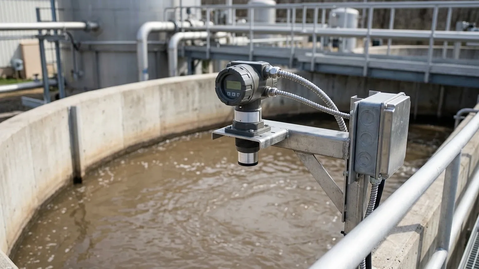
Proper installation is the single most important factor in the performance of an ultrasonic level sensor and transmitter. Even the most advanced sensor will fail if it is poorly positioned.
Orientation and Positioning
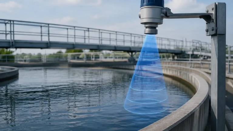
* Perpendicularity: The sensor must be installed perfectly perpendicular to the liquid surface. If the sensor is tilted, the sound waves will bounce off the surface at an angle and may not return to the receiver.
* Avoid the Center: In cylindrical tanks with domed tops, do not install the sensor in the exact center. This can cause a "parabolic effect" where multiple echoes converge, leading to false readings.
* Clearance from Walls: Maintain a distance from the tank wall to prevent the ultrasonic beam from hitting the wall or internal ladder rungs. As a rule of thumb, stay at least 200mm (8 inches) away from the wall for every 1 meter of depth.
Obstructions
Internal structures like agitators, heating coils, or support beams can create "false echoes." While many Welk transmitters feature "false echo suppression" software to ignore these static reflections, it is always best to choose a mounting location with a clear line of sight to the material surface.
Mounting Nozzles
If the sensor is mounted on a standpipe or nozzle, the diameter and length of that pipe must be considered. If the pipe is too long or narrow, the ultrasonic pulse will bounce off the inside of the pipe before it even reaches the tank. Ensure the nozzle is short enough that the beam clears the bottom edge of the pipe.
Limitations and Environmental Factors
While versatile, ultrasonic technology has physical limitations that may necessitate switching to other technologies like radar level meters or hydrostatic transmitters.
1. Vacuum Conditions: Sound requires a medium (air or gas) to travel. Ultrasonic sensors cannot function in a vacuum.
2. Heavy Foam: Thick, dense foam on the surface of a liquid acts as an acoustic absorber. It soaks up the sound pulse instead of reflecting it, causing the sensor to lose the signal.
3. High Pressure: High-pressure environments change the density of the gas in the tank, which significantly alters the speed of sound beyond what standard temperature compensation can handle.
4. Dust and Vapor: While light dust is manageable, extremely heavy dust (like in a cement silo during filling) or heavy steam can scatter the ultrasonic signal.
Frequently Asked Questions (FAQs)
Q: Can ultrasonic level meters be used for solids?
A: Yes, but with caveats. Solids like grain, sand, or plastic pellets do not reflect sound as efficiently as liquids. They also tend to form conical shapes (angle of repose) rather than a flat surface. For solids, it is recommended to use a sensor with a higher power output and a narrower beam angle.
Q: How do I handle turbulence in the tank?
A: Through software and hardware. Most modern transmitters allow for "damping" or "averaging," which smooths out the reading if the surface is wavy. Alternatively, a stilling well (a vertical pipe) can be used to provide a calm surface for the measurement.
Q: Is the sensor affected by the color or transparency of the liquid?
A: No. Unlike optical or laser sensors, ultrasonic waves are purely mechanical. The color, transparency, or opacity of the liquid has zero effect on the measurement accuracy.
Q: What is the typical lifespan of an ultrasonic transmitter?
A: With no moving parts, these devices are exceptionally durable. In standard water treatment applications, a lifespan of 7 to 10 years is common, provided the housing materials are correctly matched to the environment.
Conclusion
The ultrasonic level sensor and transmitter remains a preferred choice for industrial level monitoring due to its non-contact nature and ease of integration. By understanding the acoustic principles and adhering to strict installation guidelines regarding beam angles and dead zones, engineers can achieve highly accurate and maintenance-free operation.
For projects requiring specialized configurations or OEM services, Welk provides robust Ultrasonic Level Meters tailored to specific industrial demands. When selecting your next instrument, ensure that the environmental conditions—specifically temperature, pressure, and surface consistency—align with the strengths of ultrasonic technology to ensure long-term system reliability.