Ultrasonic Level Sensor Beam Angle
Understanding Ultrasonic Level Sensor Beam Angle: A Technical Guide for Process Engineering
In industrial level measurement, selecting the right technology is only the first step toward achieving reliable process control. For many engineers, Ultrasonic Level Meters are the preferred choice due to their non-contact nature, ease of installation, and cost-effectiveness. However, one of the most critical yet frequently misunderstood technical specifications is the ultrasonic level sensor beam angle.
Choosing a sensor with an inappropriate beam angle can lead to false readings, signal loss, and inconsistent data, particularly in confined spaces or tanks with internal obstructions. This guide provides a comprehensive analysis of beam angle physics, its impact on measurement accuracy, and practical selection criteria for industrial applications.
Measurement Principles of Ultrasonic Technology
Before diving into the specifics of beam angles, it is essential to understand how Ultrasonic Level Meters function. These instruments operate on the Time-of-Flight (ToF) principle.
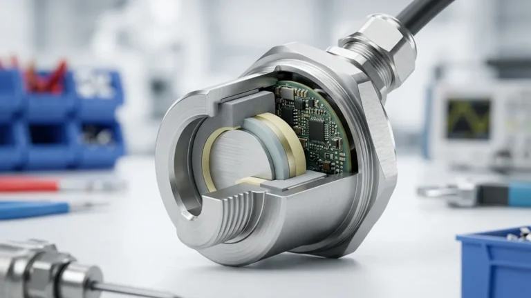
1. Pulse Emission: A piezoelectric transducer within the sensor head converts electrical energy into mechanical vibrations, emitting a burst of ultrasonic sound waves (typically between 20 kHz and 200 kHz).
2. Propagation: These sound waves travel through the air or gas medium toward the surface of the material being measured.
3. Reflection: Upon hitting the liquid or solid surface, a portion of the acoustic energy is reflected back toward the sensor.
4. Detection and Calculation: The transducer receives the returning echo. The onboard electronics calculate the distance based on the time elapsed between emission and reception, using the speed of sound in the specific medium.
The Formation of the Beam
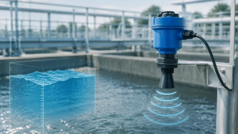
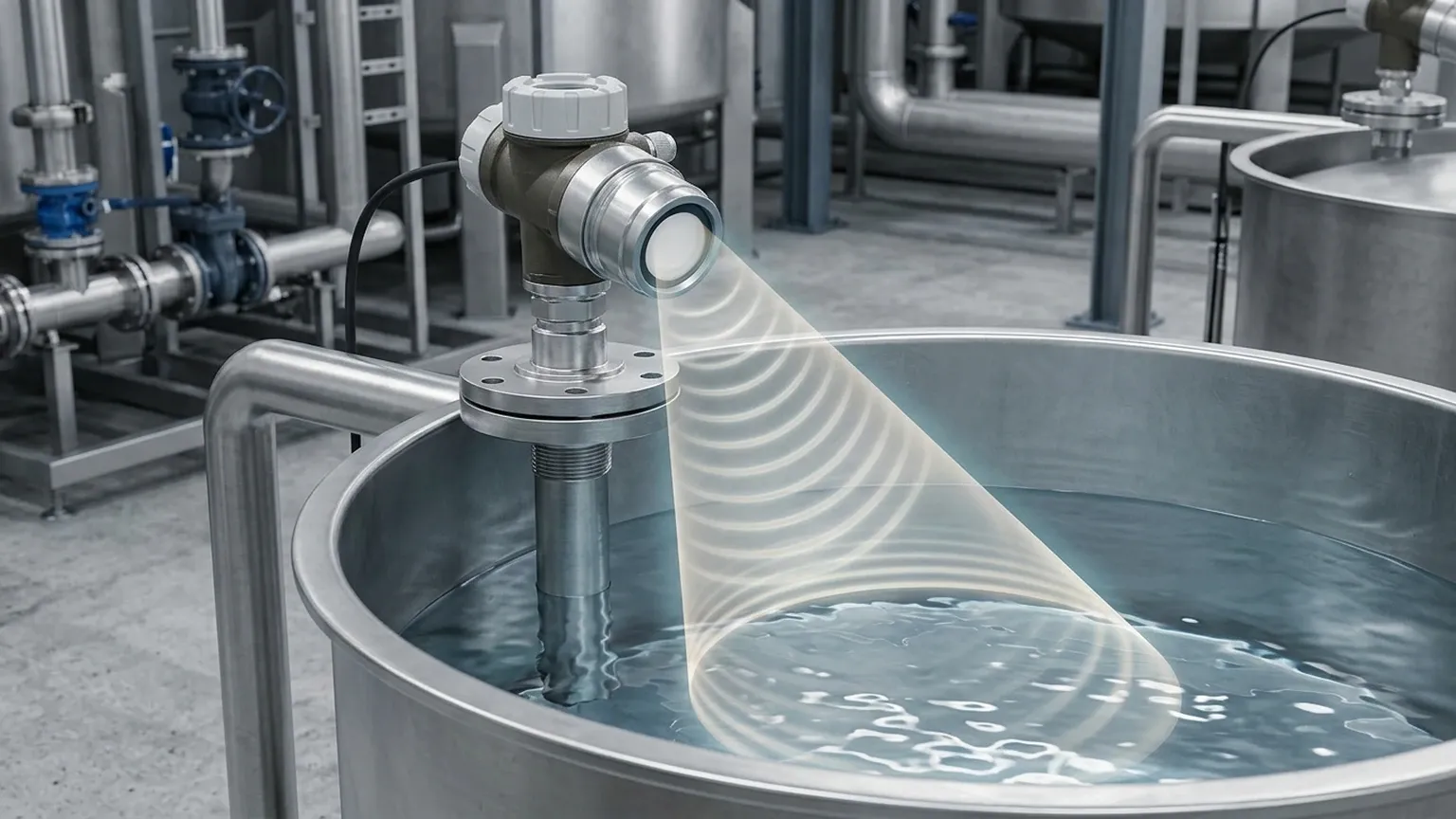
Unlike a laser, which produces a highly collimated and narrow light path, an ultrasonic pulse spreads out as it travels away from the transducer. This spreading creates a conical shape known as the "beam." The intensity of the sound energy is highest at the center axis of this cone and gradually diminishes toward the edges.
What is the Ultrasonic Level Sensor Beam Angle?
The ultrasonic level sensor beam angle is technically defined as the angle at which the sound pressure level drops to 50% (or -3dB) of its peak intensity at the center of the beam.
It is important to note that sound energy does exist outside of this defined angle, often referred to as "side lobes." While the primary measurement occurs within the main beam, high-reflectivity objects (like metal rungs or agitator blades) located just outside the theoretical beam angle can still cause interference if the sensor's sensitivity is set too high.
Calculating the Beam Footprint
To ensure a successful installation, engineers must calculate the diameter of the "footprint" the beam will cover at the maximum distance (the bottom of the tank). The formula for the radius ($R$) of the beam at a distance ($D$) is:
$$R = D \times \tan(\alpha / 2)$$
Where $\alpha$ is the beam angle provided by the manufacturer.
For example, if a Welk ultrasonic sensor has a 10° beam angle and the tank is 6 meters (approx. 19.7 ft) deep, the radius of the beam at the bottom would be approximately 0.52 meters (1.7 ft), resulting in a total beam diameter of 1.04 meters (3.4 ft). Any obstruction within this 1.04-meter circle could potentially reflect the signal and cause a false level reading.
The Relationship Between Frequency and Beam Angle
In ultrasonic sensor design, there is an inverse relationship between the transducer frequency and the beam angle.
* Low-Frequency Sensors (e.g., 20 kHz – 40 kHz): These sensors are designed for long-range measurements (up to 30 or 40 meters). Because they require larger transducers to produce lower frequencies, they often have wider beam angles, typically ranging from 10° to 15°.
* High-Frequency Sensors (e.g., 60 kHz – 100+ kHz): These are used for shorter ranges (0.1 to 10 meters). Higher frequencies allow for smaller transducers and more focused, narrower beam angles, often between 5° and 8°.
Narrower beam angles are generally preferred in industrial settings because they allow the sensor to "see" through narrow openings or avoid internal tank structures.
Selection Criteria: Narrow vs. Wide Beam Angles
Selecting the correct beam angle depends entirely on the geometry of the vessel and the nature of the application.
When to Choose a Narrow Beam Angle (5° – 8°)
* Tall, Narrow Silos: To avoid reflections from the side walls.
* Internal Obstructions: When the tank contains agitators, heating coils, ladders, or support struts.
* Stilling Wells: When measuring level inside a pipe or bypass chamber.
* Precision Requirements: Narrower beams focus more energy on the target, often resulting in a stronger return signal in dusty or slightly turbulent environments.
When to Choose a Wide Beam Angle (10° – 15°)
* Open Channels and Sumps: Where there are no walls or obstructions to interfere with the signal.
* Uneven Solid Surfaces: In grain or coal storage, a wider beam can average out the peaks and valleys of the material surface for a more stable reading.
* Large Storage Tanks: Where the sensor is mounted far from any walls and the surface is relatively calm.
Practical Selection Table
| Application Type | Recommended Beam Angle | Key Consideration |
| :— | :— | :— |
| Standard Liquid Storage (No obstructions) | 10° – 12° | Cost-effective, standard performance. |
| Process Vessel with Agitator | 5° – 8° | Must avoid blades and shaft reflections. |
| Narrow Pipe or Stilling Well | < 6° | Prevents "ringing" or wall interference. |
| Open Sump / Wastewater | 12° – 15° | High tolerance for sensor positioning. |
| Solid/Bulk Solids (Silos) | 8° – 10° | Balance between focus and surface averaging. |
Installation Considerations and Best Practices
Even the best Ultrasonic Level Meters will fail if the installation does not account for the beam angle. Follow these engineering guidelines to ensure optimal performance:
1. Distance from the Wall
A common rule of thumb is to mount the sensor at a distance from the tank wall that is at least 1/10th of the total tank height. However, a more precise method is to use the beam footprint calculation mentioned earlier. Ensure that the edge of the beam (based on the half-angle) does not intersect the wall. If the beam hits a rough wall, the signal will scatter; if it hits a smooth wall, it may bounce to the liquid surface and back to the wall, creating a "multipath" error.
2. Avoiding Obstructions
The beam path must be clear of any fixed or moving objects. If an obstruction is unavoidable, many modern Welk sensors include "False Echo Suppression" or "Echo Masking" software. This allows the user to tell the sensor to ignore reflections at a specific distance. However, this should be a secondary solution; physical clearance is always superior.
3. Perpendicular Alignment
The sensor face must be installed perfectly parallel to the liquid surface. If the sensor is tilted, the beam angle may cause the reflected signal to bounce away from the transducer rather than back to it, leading to a "Loss of Echo" (LOE) error. For solids, where the material forms a cone, an adjustable mounting flange may be required to aim the beam at the effective center of the material slope.
4. The "Dead Zone" (Blocking Distance)
Every ultrasonic sensor has a dead zone immediately below the transducer face where it cannot measure (typically 0.2m to 0.6m depending on the model). Ensure the maximum high-level of the liquid never enters this zone, as the beam has not yet formed properly, and the transducer cannot switch from "transmit" to "receive" mode fast enough.
Limitations and Environmental Factors
While understanding the ultrasonic level sensor beam angle is vital, other factors can influence how the beam behaves:
* Temperature Gradients: Sound travels faster in warm air. Significant temperature shifts can refract (bend) the ultrasonic beam, potentially moving the footprint away from the intended target.
* Vapor and Pressure: High concentrations of heavy vapors (like solvents) or high-pressure environments change the speed of sound and can attenuate (weaken) the beam energy.
* Foam: Heavy, dense foam absorbs ultrasonic signals. In these cases, the beam angle becomes irrelevant because the energy never reflects back. A frequency-tuned sensor or a different technology (like radar) may be required.
* Turbulence: Violent surface agitation can scatter the beam. A wider beam angle might actually help in some turbulent liquid applications by catching "stray" reflections, though a stilling well is usually the better engineering fix.
Frequently Asked Questions (FAQ)
Q: Can I reduce the beam angle of my sensor with a nozzle?
A: No. In fact, mounting a sensor in a long, narrow nozzle can cause "ringing" where the sound waves bounce off the nozzle walls before even entering the tank, creating a massive dead zone. Always ensure the sensor face extends slightly past the bottom of the mounting nozzle.
Q: Does a narrower beam angle mean more accuracy?
A: Not necessarily. Accuracy is determined by the electronics and frequency. A narrower beam simply means the sensor is more selective about where it gathers data, which improves reliability in complex environments.
Q: How do I know if my beam angle is hitting an obstruction?
A: Most professional ultrasonic meters provide an echo curve (envelope curve) display. If you see a large, static peak at a distance that doesn't change when the liquid level moves, the beam is likely hitting an internal structure.
Q: Is the beam angle the same for solids and liquids?
A: The physical angle emitted by the transducer is the same. However, because solids (like sand or plastic pellets) scatter sound more than liquids, you effectively have a "weaker" beam, making proper alignment and a focused beam angle even more critical.
Conclusion
Successful level measurement relies on matching the instrument's physical characteristics to the vessel's environment. The ultrasonic level sensor beam angle is a fundamental parameter that dictates where a sensor can be placed and what obstacles it can tolerate. By calculating the beam footprint and adhering to strict installation distances, engineers can leverage the full potential of Ultrasonic Level Meters to provide accurate, maintenance-free monitoring.
For complex applications involving internal agitators or narrow geometries, consulting with a manufacturer like Welk can help identify the ideal frequency and beam angle configuration. For more detailed specifications and product comparisons, you can Review product options and application support to find the right solution for your industrial requirements.