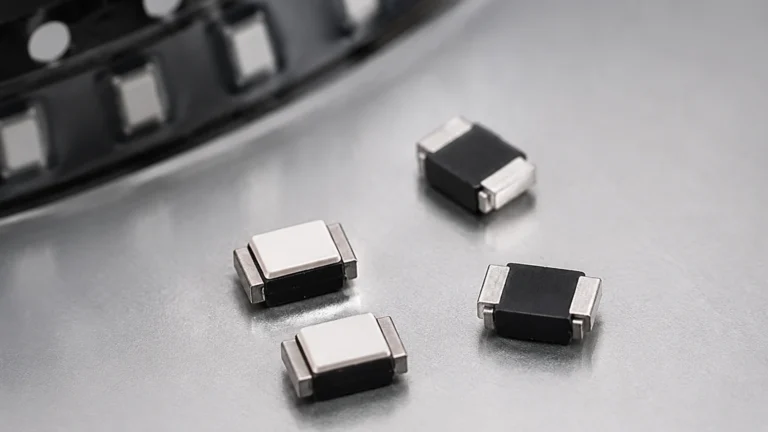
Tank Level Pressure Sensor
Tank Level Pressure Sensor
In the landscape of industrial process control, the tank level pressure sensor—often referred to as a hydrostatic level transmitter—remains one of the most reliable and widely implemented technologies for monitoring liquid inventory. By leveraging the fundamental relationship between the height of a liquid column and the pressure it exerts at a specific depth, these instruments provide a robust solution for water treatment, chemical processing, and oil and gas storage.
For engineers and facility managers, selecting the correct tank level pressure sensor requires a deep understanding of fluid dynamics, material compatibility, and the physical constraints of the storage vessel. This guide provides a comprehensive technical overview of hydrostatic measurement principles, sensor types, and the practical considerations necessary for successful deployment.
Understanding the Measurement Principle
The operation of a tank level pressure sensor is based on the principle of hydrostatic pressure. According to Pascal’s Law, the pressure at any point within a static fluid is determined by the weight of the liquid column above it. This relationship is mathematically expressed as:
P = ρ × g × h
Where:
* P is the hydrostatic pressure (typically measured in bar, kPa, or psi).
* ρ (rho) is the density of the liquid (kg/m³ or lb/ft³).
* g is the local acceleration due to gravity (approximately 9.81 m/s²).
* h is the height of the liquid column (meters or feet).
In most industrial applications, gravity is considered a constant. Therefore, if the density of the liquid remains stable, the pressure measured at the bottom of the tank is directly proportional to the liquid level. For example, a water column (with a density of 1,000 kg/m³) of 10 meters (32.8 ft) will exert a pressure of approximately 0.98 bar (14.2 psi) at the base. By measuring this pressure, the sensor’s electronics can calculate and output the exact level via a 4-20mA, HART, or RS485 Modbus signal.
Types of Tank Level Pressure Sensors
Depending on the tank geometry and the nature of the liquid, sensors are generally categorized into two primary mounting configurations: submersible and externally mounted.
1. Submersible Level Transmitters
Often called "drop-in" sensors, these units consist of a sensing element housed in a waterproof casing (usually 316L stainless steel) that is lowered directly into the liquid. The sensor is connected to a specialized cable that contains a vent tube. This tube allows the sensor to reference atmospheric pressure, ensuring that changes in barometric pressure do not affect the accuracy of the level reading.
2. Externally Mounted (Threaded or Flanged)
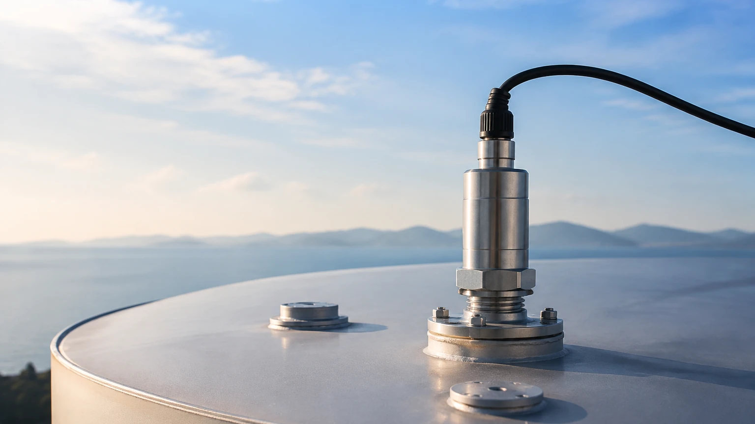
These sensors are installed through a nozzle or tapping point at the bottom or side of the tank. They are preferred for closed tanks or applications where the sensor must be isolated from the process for maintenance without emptying the vessel. They utilize a diaphragm that sits flush with the tank wall, making them suitable for viscous liquids that might clog a submersible sensor's protective cap.
3. Differential Pressure (DP) Transmitters
In pressurized vessels, such as boilers or chemical reactors, the total pressure at the bottom of the tank includes both the liquid's hydrostatic pressure and the gas pressure in the headspace. A standard tank level pressure sensor would provide an incorrect reading in this scenario. A DP transmitter measures the difference between the bottom pressure and the headspace pressure, effectively "canceling out" the gas pressure to isolate the liquid level.
Technical Selection Criteria
Choosing the right instrument involves evaluating several environmental and process variables. The following table provides a baseline for comparing common sensor configurations:
| Feature | Submersible Sensors | External Gauge Sensors | Differential Pressure Sensors |
| :— | :— | :— | :— |
| Best Use Case | Deep wells, open reservoirs, lift stations | Vented storage tanks, clean liquids | Pressurized tanks, boilers, liquefied gas |
| Installation | Suspended by cable | Threaded or flanged process connection | Dual process connections (High/Low) |
| Maintenance | Easy to pull up and clean | Requires tank isolation valves | Complex piping/manifold required |
| Media Compatibility | Water, wastewater, fuel | Chemicals, oils, food products | High-pressure gases and liquids |
| Typical Range | 0–1m to 0–500m | 0–0.1 bar to 0–40 bar | Custom DP ranges |
Material Compatibility
The wetted parts of the sensor must be chemically compatible with the stored media. While 316L stainless steel is the standard for water and light oils, more aggressive chemicals may require:
* Ceramic Diaphragms: Highly resistant to abrasion and many acids.
* Tantalum or Hastelloy C: Required for highly corrosive environments like hydrochloric or sulfuric acid.
* PTFE/FEP Cables: Used for submersible sensors in chemical tanks to prevent cable degradation.
Installation Considerations and Best Practices
Proper installation is critical to the longevity and accuracy of a tank level pressure sensor. Engineers should adhere to the following guidelines:
Positioning and Turbulence
Sensors should be installed away from pump inlets, agitators, or fill pipes. Turbulent flow can cause pressure fluctuations that lead to erratic level readings. If turbulence is unavoidable, a "stilled pipe" or "stilling well" (a perforated PVC or metal pipe) should be used to protect the sensor and provide a stable liquid column for measurement.
Atmospheric Venting
For submersible sensors, the vent tube in the cable must remain unobstructed. If moisture enters the vent tube, it can lead to internal corrosion or sensor drift. It is recommended to use a junction box with a breathable desiccant filter to prevent humidity from entering the tube while still allowing for atmospheric pressure compensation.
Overpressure Protection
Always select a sensor with an overpressure rating that exceeds the maximum possible pressure in the system (including potential pressure spikes from valve closures or pump starts). A common industry standard is to choose a sensor with a burst pressure at least 2 to 3 times the working range.
Mounting Height
In tanks where sediment or sludge accumulates at the bottom, the sensor should be mounted slightly above the floor. This prevents the diaphragm from being buried in debris, which would cause false high-pressure readings and potential mechanical damage.
Limitations and Accuracy Factors
While hydrostatic sensors are versatile, they have inherent limitations that must be managed:
1. Density Sensitivity: Since the sensor measures weight, any change in the liquid's density will change the level reading. For example, if a tank's temperature rises significantly, the liquid may expand and its density decrease. The sensor will report a lower level even if the volume remains the same. In such cases, temperature compensation or integrated temperature sensors are necessary.
2. Vessel Type: Hydrostatic sensors are not naturally suited for vacuum tanks unless specialized differential pressure transmitters are used.
3. Mechanical Build-up: In wastewater applications, fats, oils, and grease (FOG) can build up on the sensor diaphragm. Regular cleaning or the use of a flush-diaphragm design is required to maintain accuracy.
Practical Engineering FAQ
Q: Can a tank level pressure sensor be used for solids?
A: No. Hydrostatic pressure principles only apply to liquids. For solids or powders, technologies like radar or ultrasonic sensors are required. You can Review product options and application support to find suitable alternatives for bulk solids.
Q: How do I calibrate a sensor for a liquid other than water?
A: You must apply a scaling factor based on the specific gravity (SG) of the liquid. If the liquid has an SG of 0.8 (like some oils), the pressure exerted will be 80% of what water would exert at the same height. The transmitter output must be scaled accordingly at the PLC or display unit.
Q: What is the advantage of a ceramic sensor over a stainless steel one?
A: Ceramic diaphragms are often "dry" cells, meaning they do not use an internal oil fill. They are more resistant to mechanical overloads and are often preferred in food and beverage applications where oil contamination must be avoided.
Q: How long can the cable be on a submersible sensor?
A: With a 4-20mA signal, cables can often extend up to 1,000 meters (approx. 3,280 ft) without significant signal loss, provided the wire gauge is sufficient and the power supply can overcome the loop resistance. However, the vent tube's effectiveness may decrease over extremely long distances if not properly managed.
Conclusion
The tank level pressure sensor is a cornerstone of industrial level measurement due to its simplicity and reliability. By understanding the relationship between density, height, and pressure, and by selecting materials and mounting styles appropriate for the specific environment, operators can achieve high-precision monitoring with minimal maintenance. For complex applications involving pressurized vessels or highly corrosive chemicals, consulting with a specialized manufacturer like Welk ensures that the instrumentation is tailored to the rigors of the process.
Before finalizing a system design, always confirm the chemical compatibility of all wetted parts and ensure that the installation environment allows for proper atmospheric venting and protection from mechanical turbulence. For further technical specifications and to explore a wide range of industrial measurement solutions, visit the Welk Main Page.