Water Level Controller
Water Level Controller
In industrial fluid management, a water level controller is a critical component used to automate the monitoring and regulation of liquid levels within tanks, reservoirs, and process vessels. These systems integrate sensing technologies with control logic to prevent overflows, protect pumps from dry running, and ensure that process parameters remain within specified limits. For engineers and facility managers, selecting the appropriate water level controller requires a deep understanding of measurement principles, the physical properties of the medium, and the specific requirements of the application environment.
Effective water level control is not merely about turning a pump on or off; it involves a sophisticated chain of data acquisition and response. This guide explores the fundamental technologies behind these instruments, provides selection criteria for industrial environments, and outlines best practices for installation and maintenance.
Principles of Level Measurement for Controllers
Before a controller can execute a command, it must receive an accurate signal from a level sensor. Industrial water level controllers typically rely on one of several core measurement principles, each suited to different operational constraints.
Hydrostatic Pressure Measurement
The hydrostatic principle is based on the relationship between the height of a liquid column and the pressure exerted at the base. The formula $P = \rho \cdot g \cdot h$ (where $P$ is pressure, $
ho$ is density, $g$ is gravity, and $h$ is height) allows the sensor to determine the level by measuring the weight of the water above it. This method is highly effective for deep wells and large open reservoirs. Submersible pressure transmitters are commonly used here, providing a stable 4-20mA signal to the controller.
Ultrasonic (Time-of-Flight)
Ultrasonic sensors are non-contact devices that emit high-frequency sound pulses. These pulses reflect off the surface of the water and return to the sensor. By measuring the time taken for the pulse to travel the round trip, the device calculates the distance to the water surface. This technology is ideal for wastewater and corrosive liquids where contact with the medium should be avoided. However, it can be affected by heavy foam or significant temperature fluctuations that alter the speed of sound.
Radar Level Measurement
Radar sensors operate similarly to ultrasonic devices but use electromagnetic waves (microwave) instead of sound. Radar is largely unaffected by vacuum, high pressure, or temperature variations. It is the preferred choice for high-precision industrial applications, such as chemical processing or high-pressure boilers. Both Pulse Radar and Frequency Modulated Continuous Wave (FMCW) radar provide exceptional accuracy over long distances.
Magnetic and Float-Based Sensing
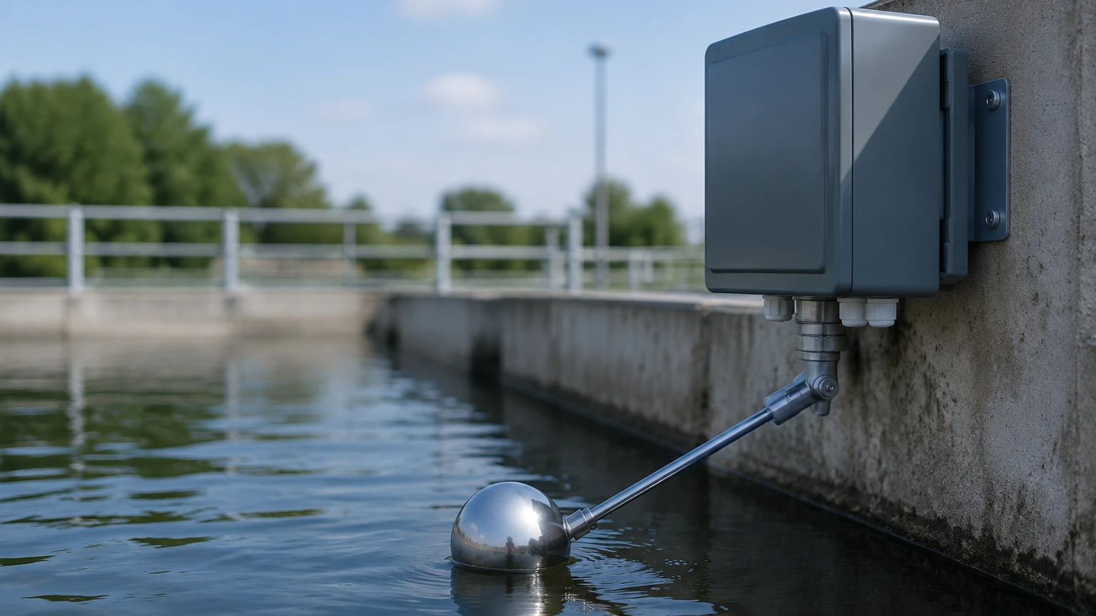
Magnetic level gauges and float switches use buoyancy to track the water level. A float containing a magnet moves with the liquid level, actuating reed switches or providing a continuous signal via a resistance chain. These are purely mechanical or electromechanical and are prized for their reliability in high-temperature or high-pressure tanks where electronic components might fail if directly exposed to the process.
Types of Water Level Controllers
Industrial controllers vary in complexity based on the level of automation required. They generally fall into three categories:
1. Point-Level Controllers (Switching): These are used to detect specific levels (e.g., High-High, High, Low, Low-Low). When the water reaches a sensor, the controller triggers a relay to start or stop a pump or open/close a valve. These are common in sump pump applications and basic tank filling operations.
2. Continuous Level Controllers: These receive a constant stream of data (usually a 4-20mA or 0-10V signal) and provide real-time monitoring. They allow for more nuanced control, such as modulating a valve to maintain a precise level or calculating the volume of liquid remaining in a tank.
3. Integrated PLC/SCADA Systems: In large-scale industrial automation, the "controller" is often a Programmable Logic Controller (PLC) that manages multiple tanks and processes simultaneously. The level sensors feed data into the PLC, which then coordinates with other system variables to optimize plant efficiency.
Key Evaluation Criteria for Selection
Selecting the right water level controller involves more than just matching a sensor to a tank. Engineers must evaluate the following technical factors:
* Accuracy and Repeatability: For inventory management, high accuracy (±1mm to ±3mm) is required. For simple overflow protection, a wider tolerance may be acceptable.
* Media Characteristics: Consider the conductivity, viscosity, and chemical compatibility of the water. Deionized water, for instance, has low conductivity, making it unsuitable for conductive probes but perfect for ultrasonic or radar sensors.
* Environmental Conditions: The controller and sensor must withstand the ambient environment. This includes IP ratings (e.g., IP68 for submersible units), explosion-proof ratings (ATEX/IECEx) for hazardous zones, and operating temperature ranges (typically -40°C to +80°C for standard industrial units).
* Output and Communication: Modern systems often require more than a simple relay. Look for controllers that support Modbus RTU (RS485), HART protocol, or Profibus for seamless integration into digital industrial networks.
Technical Selection Table
The following table provides a quick reference for matching measurement technologies with specific application needs.
| Technology | Contact Type | Best Application | Limitations | Typical Accuracy |
| :— | :— | :— | :— | :— |
| Hydrostatic | Contact | Deep wells, open tanks | Sensitive to density changes | ±0.25% to ±0.5% |
| Ultrasonic | Non-contact | Wastewater, sumps | Affected by foam and steam | ±0.25% of range |
| Radar | Non-contact | Chemical tanks, high pressure | Higher initial cost | ±1mm to ±3mm |
| Magnetic Float | Contact | High-temp boilers | Mechanical wear over time | ±5mm to ±10mm |
| Capacitance | Contact | Small vessels, oils | Requires constant dielectric | ±1% |
Installation and Maintenance Considerations
Proper installation is paramount to the longevity and accuracy of a water level controller. Even the most advanced radar sensor will fail if placed incorrectly.
Positioning and Dead Zones
Non-contact sensors (ultrasonic and radar) have a "dead zone" or "blocking distance" directly beneath the sensor face where measurement is impossible. The sensor must be mounted high enough so that the maximum water level never enters this zone. Furthermore, sensors should be positioned away from the tank walls and inlet pipes to avoid false reflections or interference from turbulent water.
Stilling Wells and Bypass Chambers
In tanks with significant agitation or surface turbulence, a stilling well (a pipe that extends into the liquid) can be used to provide a calm surface for the sensor. For magnetic gauges, a bypass chamber mounted to the side of the tank allows for maintenance without depressurizing the main vessel.
Wiring and Signal Integrity
Industrial environments are often rife with electromagnetic interference (EMI). Using shielded cables and ensuring proper grounding is essential to prevent signal drift in 4-20mA loops. For long-distance transmissions (over 500 meters), digital protocols like RS485 are recommended over analog signals to maintain data integrity.
Common Risks and Limitations
While modern water level controllers are robust, they are not immune to failure. Awareness of these risks allows for better system design:
* Build-up and Scaling: In hard water or chemical applications, material can build up on the sensor face or float. This can cause "frozen" readings or signal attenuation. Regular cleaning schedules are necessary for contact-based and ultrasonic sensors.
* Turbulence and Surface Agitation: Rapidly moving water can cause unstable readings. Controllers with adjustable damping or "fuzzy logic" can filter out this noise, but physical solutions like stilling wells are often more effective.
* Vapor and Condensation: In closed tanks, condensation can form on the sensor lens. Some high-end radar sensors feature drip-off lens designs or air purging systems to mitigate this issue.
Frequently Asked Questions (FAQs)
Q: Can one water level controller manage multiple pumps?
A: Yes, many digital controllers feature multiple relay outputs (e.g., 2 to 4 relays) that can be programmed for pump alternation (lead-lag) to ensure even wear across multiple pump units.
Q: How often should a water level controller be calibrated?
A: For critical process applications, annual calibration is standard. For general monitoring, a check every two years is usually sufficient, provided there is no significant drift or change in the media density.
Q: Is radar always better than ultrasonic?
A: Not necessarily. While radar is more precise and handles steam/vacuum better, ultrasonic is often more cost-effective for simple water and wastewater applications where the environment is stable.
Conclusion
A robust water level controller is the backbone of efficient industrial fluid management. By understanding the physics of measurement—whether through hydrostatic pressure, sound, or electromagnetic waves—engineers can implement systems that reduce waste, prevent equipment damage, and ensure safety. When selecting a system, it is vital to consult with a professional manufacturer to ensure the hardware matches the specific chemical and physical demands of your facility. For more detailed specifications and to explore a wide range of industrial measurement instruments, you can visit the Main Page to review product options and application support.