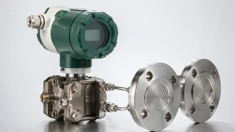
Ma Hart
Ma Hart
In the landscape of industrial automation and process control, the communication protocol used by field instruments determines the efficiency of data acquisition and device management. Among the most prevalent standards in level measurement is the combination of the 4-20 mA analog signal and the HART (Highway Addressable Remote Transducer) protocol, often referred to in technical shorthand as mA HART. This hybrid communication method allows for the simultaneous transmission of a traditional analog signal and a digital data stream over the same pair of wires, providing a robust bridge between legacy systems and modern digital diagnostics.
For engineers and plant operators utilizing Welk level measurement solutions, understanding the nuances of mA HART is essential for optimizing vessel monitoring, ensuring sensor accuracy, and implementing predictive maintenance strategies. This guide explores the principles, applications, and practical considerations of deploying mA HART-enabled instruments in industrial environments.
Measurement Principles of mA HART
The mA HART protocol operates on the principle of Frequency Shift Keying (FSK). To understand how this works, one must first look at the two layers of communication happening on a single twisted-pair cable.
The Analog Layer (4-20 mA)
In a standard industrial loop, the level sensor (the transmitter) regulates the current in the circuit to represent the process variable. A current of 4 mA typically represents 0% of the measured range (e.g., an empty tank), while 20 mA represents 100% (e.g., a full tank). This analog signal is continuous, robust against electrical noise, and can travel long distances without significant signal degradation.
The Digital Layer (HART)
The HART protocol superimposes a low-level digital signal on top of the 4-20 mA analog signal. This digital signal uses the Bell 202 standard to modulate frequencies:
* 1200 Hz represents a logic "1".
* 2200 Hz represents a logic "0".
Because the average value of these high-frequency sine waves is zero, the digital signal does not interfere with the 4-20 mA analog value. This allows the primary process variable (the level) to be read by the control system via the analog current, while secondary information—such as sensor temperature, electronics health, and device configuration—is transmitted digitally.
Integration with Level Measurement Technologies
Welk incorporates mA HART technology across its primary product lines to enhance the functionality of various level sensing methods. Each technology utilizes the protocol to solve specific application challenges.
Radar Level Meters
Radar level transmitters, particularly high-frequency 80GHz models, generate vast amounts of diagnostic data. Using mA HART, these devices can transmit signal-to-noise ratios and echo profiles to a remote workstation. This allows engineers to distinguish between the actual material surface and internal tank obstructions like agitators or heating coils without being physically present at the tank top.
Ultrasonic Level Sensors
Ultrasonic sensors are sensitive to environmental factors such as foam, dust, and temperature fluctuations. Through mA HART communication, operators can remotely adjust the "blanking distance" (the zone near the sensor where measurements are ignored) and sensitivity settings. This is particularly useful in water treatment facilities where sensors may be mounted in hard-to-reach locations over open channels or deep wet wells.
Hydrostatic Level Transmitters
In hydrostatic pressure measurement, the density of the liquid directly affects the level calculation. mA HART allows for the digital input of density corrections and the remote calibration of zero and span points. If a process fluid changes—for instance, switching from water to a chemical with a different specific gravity—the transmitter can be updated via the HART protocol without removing it from the process line.
Key Evaluation Criteria for mA HART Systems
When selecting a level measurement system that utilizes mA HART, several technical factors must be evaluated to ensure compatibility with existing infrastructure.
1. Device Description (DD) and DTM Files: To fully access the digital features of a HART device, the host system (PLC, DCS, or handheld communicator) must have the correct Device Description file. This file acts as a driver, telling the system how to interpret the digital data from the specific Welk sensor model.
2. Loop Resistance: For the digital HART signal to be readable, the loop must have a minimum resistance, typically 250 ohms. This resistance is necessary to develop a sufficient voltage drop for the HART modem to detect the FSK signal. If the control system's input impedance is too low, an external resistor must be added.
3. Update Rates: While the analog 4-20 mA signal is instantaneous, the HART digital data rate is relatively slow at 1200 bps. Therefore, HART should be used for configuration and diagnostics rather than high-speed control loops where sub-second response times are required for the digital data.
Practical Selection Table
The following table compares mA HART with other common communication protocols used in level measurement to assist in the selection process.
| Feature | Standard 4-20 mA | mA HART | Modbus RTU (RS485) | Foundation Fieldbus |
| :— | :— | :— | :— | :— |
| Signal Type | Analog Only | Analog + Digital | Digital Only | Digital Only |
| Wiring | 2-Wire (Loop Powered) | 2-Wire (Loop Powered) | 4-Wire (Usually) | 2-Wire (Bus Powered) |
| Multi-drop Support | No | Yes (up to 64 devices) | Yes (up to 247) | Yes (up to 32) |
| Diagnostics | Limited (Error mA) | Comprehensive | Comprehensive | Advanced/Predictive |
| Configuration | Local (Buttons/Pots) | Remote & Local | Remote | Remote |
| Cable Length | Up to 1,500m | Up to 1,500m | Up to 1,200m | Up to 1,900m |

Installation and Commissioning Considerations
Successful deployment of mA HART instruments requires adherence to specific installation standards to prevent signal interference and ensure reliable data transmission.
Cabling and Grounding
Standard unshielded twisted-pair wire is often sufficient for short distances, but for industrial environments with high electromagnetic interference (EMI), shielded twisted-pair cable is mandatory. The shield should be grounded at only one point—typically at the control cabinet—to avoid ground loops that can introduce noise into the mA HART signal.
Power Supply Requirements
Level transmitters require a stable power supply, usually 24V DC. When using mA HART, ensure the power supply is "clean." Switching power supplies can sometimes introduce high-frequency noise that overlaps with the 1200/2200 Hz HART frequencies, causing communication errors. Using a dedicated power filter or a linear power supply can mitigate these issues.
Point-to-Point vs. Multi-drop Mode
* Point-to-Point: This is the most common configuration. One sensor is connected to one control system input. The 4-20 mA signal functions normally, and digital communication occurs simultaneously.
* Multi-drop: In this mode, multiple sensors (up to 64 in HART 7) are connected in parallel on a single pair of wires. The analog current is fixed at a minimum value (usually 4 mA), and all process data is transmitted digitally. This saves on wiring costs but sacrifices the speed and simplicity of the analog signal.
To explore specific hardware configurations and sensor types, you can Review product options and application support on the Welk Main Page.
Limitations and Common Risks
While mA HART is a versatile protocol, it is not without limitations. Engineers should be aware of the following risks during the design phase:
* Slow Digital Communication: As mentioned, the 1200 bps baud rate is slow. Retrieving a full echo curve from a radar level meter via HART can take several seconds or even minutes. For real-time visualization of complex data, digital protocols like Profibus or industrial Ethernet may be more appropriate.
* Capacitance Limits: The maximum length of the cable is limited by the total capacitance of the loop. Excessive capacitance (from very long cables or low-quality insulation) can "round off" the FSK square waves, making the digital data unreadable.
* Interoperability Issues: Although HART is a standard, different versions (HART 5, 6, and 7) exist. Ensure that your handheld communicator or gateway supports the version implemented in the level sensor.
Frequently Asked Questions (FAQs)
Q: Can I use a standard multimeter to read the HART digital signal?
A: No. A standard multimeter will only measure the average DC current (the 4-20 mA signal). To read the digital data, you need a HART-compatible handheld communicator, a HART modem connected to a PC, or a control system with a HART-enabled input card.
Q: What happens if the loop resistance is less than 250 ohms?
A: The analog 4-20 mA signal will still work perfectly, but the digital HART communication will likely fail or be highly intermittent. The HART modem requires that resistance to "see" the frequency shifts as voltage changes.
Q: Is mA HART suitable for safety-instrumented systems (SIS)?
A: Yes, many Welk level meters are SIL-rated and use the 4-20 mA signal for the safety function. The HART protocol is often used in these applications for "Write Protect" features and to perform remote partial stroke testing or diagnostics that confirm the sensor is functioning within safety parameters.
Q: How does mA HART handle cable lengths over 1,000 meters?
A: For distances exceeding 1,000 meters (approx. 3,280 ft), cable capacitance becomes the primary concern. Using low-capacitance shielded cable and ensuring a high-quality 24V DC power source is critical. In extreme cases, a HART repeater may be required to maintain signal integrity.
Final Confirmation for Project Planning
Before finalizing a project involving mA HART level measurement, the following points should be confirmed by the engineering team:
* Control System Compatibility: Does the PLC/DCS input card support HART pass-through, or is a separate HART multiplexer required?
* Environmental Noise: Are there large variable frequency drives (VFDs) or motors near the cable runs that might require enhanced shielding?
* Access Requirements: Will technicians need to configure the devices from the control room, or is local configuration at the tank sufficient?
By addressing these factors, facilities can leverage the full power of mA HART to achieve precise, reliable, and maintainable level measurement across their operations.