Float Level Sensors
Float Level Sensors
In the landscape of industrial automation and process control, float level sensors remain one of the most reliable and widely utilized technologies for liquid level detection. Despite the emergence of non-contact methods such as radar and ultrasonic measurement, the mechanical simplicity and cost-effectiveness of float-based systems ensure their continued relevance in water treatment, chemical processing, and oil and gas applications. This guide provides a technical overview of float level sensor principles, selection criteria, and installation best practices for engineering professionals.
Measurement Principles of Float Level Sensors
Float level sensors operate on the fundamental principle of buoyancy, as defined by Archimedes' Principle. A float—constructed from a material with a lower density than the process liquid—is placed within a vessel. As the liquid level rises or falls, the float moves accordingly along a guide stem or within a chamber. This mechanical movement is then converted into an electrical signal.
Point Level Detection (Float Switches)
In point level applications, the float typically contains a permanent magnet. As the float reaches a predetermined height, the magnetic field actuates a hermetically sealed reed switch located inside the stationary stem. This action completes or breaks an electrical circuit, triggering an alarm, starting a pump, or closing a valve. Because the reed switch is isolated from the process media, these sensors offer high reliability and a long service life.
Continuous Level Measurement
For continuous monitoring, two primary methods are employed:
1. Resistive Chain: The stem contains a series of reed switches and resistors. As the magnetic float moves, it closes specific switches, altering the total resistance of the circuit. This resistance change is converted into a 4-20mA or digital signal proportional to the level.
2. Magnetostrictive Technology: This is a high-precision method. A sonic pulse is sent down a magnetostrictive wire inside the stem. When this pulse interacts with the magnetic field of the float, a torsional strain wave is generated and travels back to the sensor electronics. By measuring the time-of-flight of this wave, the sensor determines the float's position with sub-millimeter accuracy.
Types of Float Level Sensors
Selecting the correct sensor requires understanding the specific mechanical configuration suited for the application environment.
Vertical Float Sensors
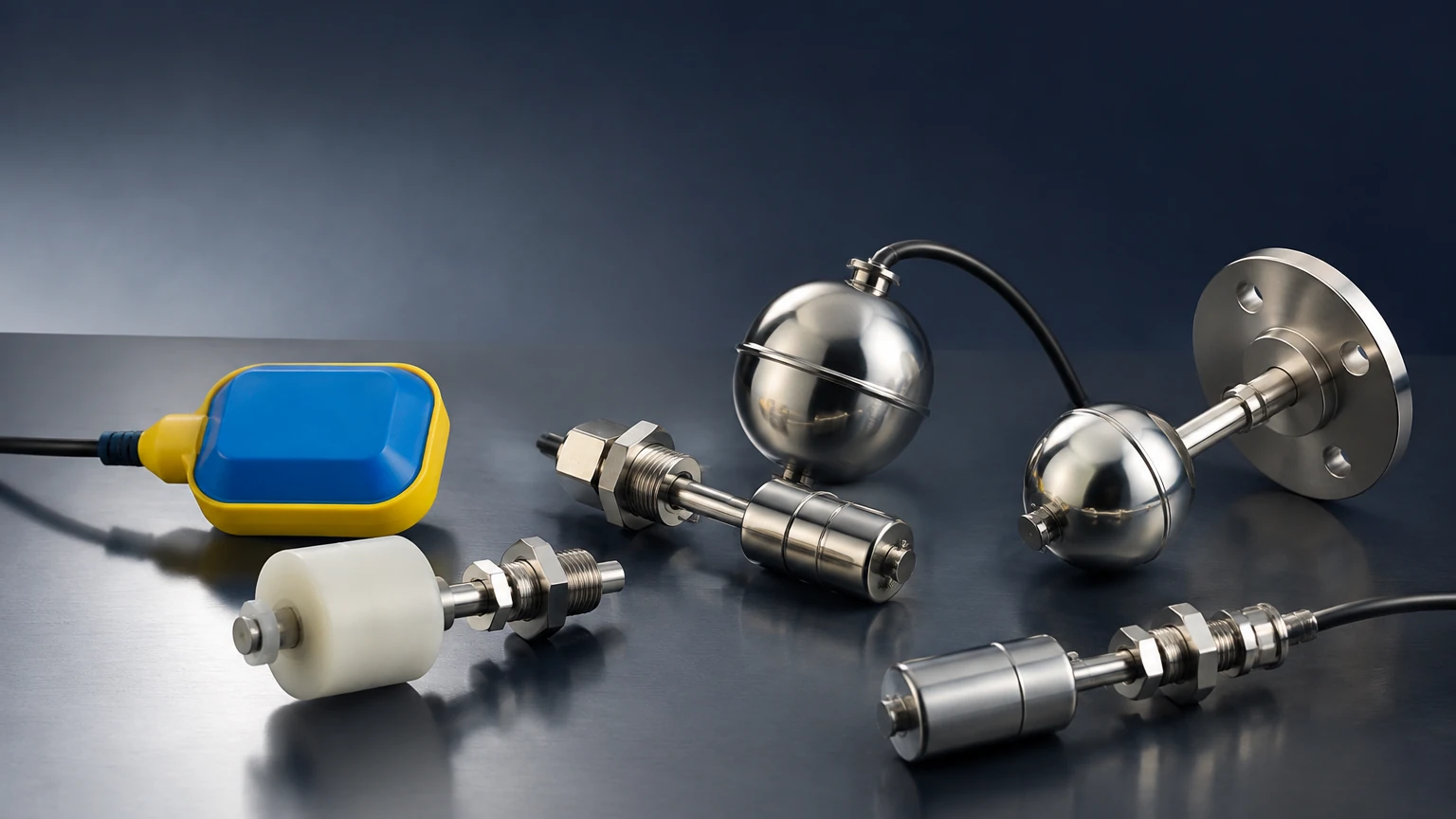
These are mounted through the top or bottom of a tank. They are ideal for deep tanks and can support multiple switching points on a single stem, allowing for high-high, high, low, and low-low level alerts in one installation.
Horizontal (Side-Mounted) Float Sensors
Side-mounted sensors are used when top access is restricted or for simple high/low limit detection. They often utilize a hinged float arm that moves an internal magnet toward a switch as the level crosses the horizontal axis.
Cable Float Switches
Commonly used in wastewater and large sumps, these sensors consist of a float attached to a flexible cable. The switching mechanism (often a microswitch or ball-bearing switch) is housed inside the float itself. As the float tilts with the rising liquid, the switch changes state.
Technical Selection Criteria
When evaluating float level sensors for an industrial project, engineers must confirm several parameters to ensure long-term performance and safety. For a broader look at how these integrate into total plant management, you may refer to the Main Page of our technical resource center.
Material Compatibility
The float and stem materials must be chemically resistant to the process fluid. Common materials include:
* 316 Stainless Steel: Suitable for high-pressure, high-temperature, and corrosive environments.
* Polypropylene (PP): Ideal for acidic or alkaline water treatment chemicals.
* PVDF/PTFE: Used for highly aggressive chemical applications where stainless steel may fail.
Specific Gravity (SG)
The float must be lighter than the liquid it is measuring. Most standard floats are designed for liquids with an SG of 0.8 or higher. For light hydrocarbons or liquefied gases, specialized high-buoyancy floats are required.
Temperature and Pressure Ratings
Industrial processes often involve extreme conditions. Stainless steel floats can typically handle pressures up to 30 bar (435 PSI) and temperatures exceeding 200°C (392°F), whereas plastic variants are usually limited to 2-5 bar and 80°C.
Comparison Table: Float Sensor Technologies
| Feature | Reed Switch (Point) | Magnetostrictive (Continuous) | Cable Float (Tilt) |
| :— | :— | :— | :— |
| Accuracy | ±3 mm to ±5 mm | ±0.1 mm to ±1 mm | Low (±20 mm+) |
| Max Pressure | Up to 40 bar | Up to 100 bar | Atmospheric |
| Maintenance | Low | Very Low | Moderate (Cable wear) |
| Typical Media | Clean liquids, oils | Fuels, chemicals | Wastewater, sumps |
| Output Type | SPST/SPDT Contact | 4-20mA, HART, Modbus | SPDT Contact |
Installation Considerations and Best Practices
Proper installation is critical to prevent mechanical failure and ensure signal integrity.
1. Avoid Turbulence: If the sensor is installed near an inlet pipe or agitator, the resulting turbulence can cause "chatter" in the switch or mechanical fatigue in the float. In these cases, a stilling well (a perforated pipe that surrounds the sensor) should be used to provide a calm surface for measurement.
2. Mounting Orientation: Vertical sensors must be installed within a specific degree of plumb (usually ±30°) to prevent the float from binding against the stem.
3. Clearance: Ensure there is sufficient overhead clearance for the removal of long stems during maintenance. If space is limited, consider segmented stems or flexible magnetostrictive probes.
4. Magnetic Interference: Since many float sensors rely on magnets, they should be kept away from strong external electromagnetic fields or large ferrous structures that could distort the magnetic field and cause false readings.
Limitations and Common Risks
While float level sensors are highly reliable, they are not universal solutions. Engineers should be aware of the following limitations:
* Fouling and Scaling: In liquids that tend to crystallize, coat, or contain heavy solids (such as thick slurries), the float may become stuck to the stem. In such environments, non-contact technologies like radar are preferred.
* Viscosity: Highly viscous fluids can slow the response time of the float or cause it to drag, leading to inaccurate readings.
* Mechanical Wear: Because they are moving parts, float sensors are subject to physical wear over millions of cycles, although magnetic coupling significantly reduces this risk compared to older mechanical linkages.
Frequently Asked Questions (FAQ)
Q: Can float level sensors be used in hazardous areas?
A: Yes. Many float switches are available with ATEX, IECEx, or UL certifications. Since reed switches are simple apparatus, they can often be used in intrinsically safe circuits with an appropriate barrier.
Q: How do I choose between a float sensor and an ultrasonic sensor?
A: Float sensors are generally better for applications with foam, heavy vapors, or vacuum conditions where ultrasonic waves might be absorbed or distorted. However, if the liquid is extremely dirty or corrosive to all float materials, a non-contact ultrasonic sensor is better.
Q: What is the maximum length for a vertical float sensor?
A: Standard rigid stems can reach up to 6 meters (approx. 20 feet). For deeper tanks, flexible probes or bypass magnetic level gauges are typically used.
Conclusion
Float level sensors remain a cornerstone of industrial level measurement due to their intuitive operation and robust performance. By carefully matching material selection, pressure ratings, and installation geometry to the specific needs of the process, facility managers can achieve highly accurate and maintenance-free level monitoring. For organizations requiring a mix of technologies—including radar, ultrasonic, and hydrostatic transmitters—consulting a comprehensive manufacturer like Welk ensures that the selected instrument is optimized for the specific chemical or physical properties of the media.
For more detailed technical specifications and to explore our full range of level measurement solutions, please visit our Main Page.